Adjustment
ADJUSTMENT
PROCEDURE
1. INSPECT AND ADJUST BRAKE PEDAL HEIGHT
(a) Remove the front door scuff plate LH.
Click here

(b) Remove the cowl side trim sub-assembly LH.
Click here 
(c) Remove the No. 1 instrument panel under cover sub-assembly.
Click here 
(d) Remove the accelerator pedal pad.
Click here 
(e) Remove the accelerator pedal.
Click here 
(f) Check the brake pedal height.
HINT:
Inspect and adjust the brake pedal height with the floor carpet and front floor mat folded back.
(1) Measure the shortest distance between the brake pedal pad surface and floor panel as shown in the illustration.
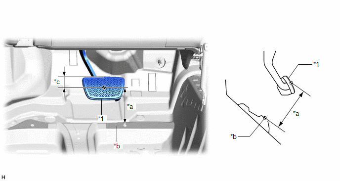
|
*1 | Brake Pedal Pad |
- | - |
|
*a | Brake Pedal Height |
*b | Measuring Plane of Floor Panel |
|
*c | 36 mm (1.42 in.) |
- | - |
Brake Pedal Height from Floor Panel:
147.5 to 161.5 mm (5.81 to 6.36 in.)
HINT:
If the brake pedal height is not as specified, inspect and adjust the push rod length according to the procedure below.
(g) Adjust the push rod length.
| (1) Remove the stop light switch assembly. Click here
 |
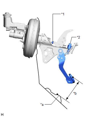 |
|
*1 | Lock Nut | |
*2 | Stop Light Switch Assembly | |
*a | Floor Panel | |
*b | Brake Pedal Height | | |
(2) Loosen the lock nut.
(3) Adjust the brake pedal height by turning the push rod.
Brake Pedal Height from Floor Panel:
147.5 to 161.5 mm (5.81 to 6.36 in.)
(4) Tighten the lock nut.
Torque:
26 N·m {265 kgf·cm, 19 ft·lbf}
(5) Install the stop light switch assembly.
Click here

(h) Install the accelerator pedal.
Click here 
(i) Install the accelerator pedal pad.
Click here 
(j) Install the No. 1 instrument panel under cover sub-assembly.
Click here 
(k) Install the cowl side trim sub-assembly LH.
Click here 
(l) Install the front door scuff plate LH.
Click here 
2. INSPECT BRAKE PEDAL FREE PLAY
(a) Stop the engine and firmly depress the brake pedal several times until no vacuum is left in the brake booster assembly.
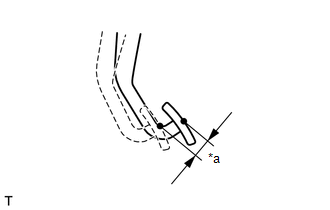
| (b) Depress the brake pedal until a slight resistance is felt. Measure the distance as shown in the illustration.
Brake Pedal Free Play: 1.0 to 6.0 mm (0.0394 to 0.236 in.)
HINT:
- If the brake pedal free play is not as specified, check the stop light switch clearance.
Click here 
- If the brake pedal free play is as specified, proceed to the Inspect Brake Pedal Reserve Distance procedure.
| |
3. INSPECT BRAKE PEDAL RESERVE DISTANCE
HINT:
Measure the distance at the same point used for the brake pedal height inspection.
(a) With the engine running, depress the brake pedal and measure the brake pedal reserve distance as shown in the illustration.
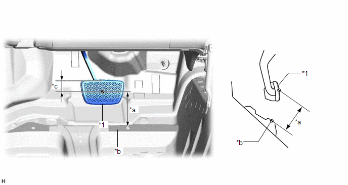
|
*1 | Brake Pedal Pad |
- | - |
|
*a | Brake Pedal Reserve Distance |
*b | Measuring Plane of Floor Panel |
|
*c | 36 mm (1.42 in.) |
- | - |
Brake Pedal Reserve Distance from Floor Panel at 300 N (31 kgf, 67.4 lbf):
81 mm (3.19 in.) or more
HINT:
If the distance is not as specified, troubleshoot the brake system.
Click here 
Components
COMPONENTS
ILLUSTRATION
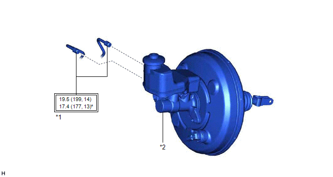
|
*1 | BRAKE LINE |
*2 | BRAKE MASTER CYLINDER SUB-ASSEMBLY |
 |
Tightening torque for "Major areas involving basic vehicle performance such as moving/turning/stopping" : N*m (kgf*cm, ft.*lbf) |
* | For use with a union nut wrench |
ILLUSTRATION
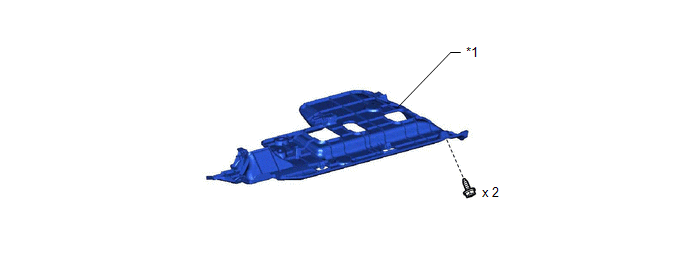
|
*1 | NO. 1 INSTRUMENT PANEL UNDER COVER SUB-ASSEMBLY |
- | - |
ILLUSTRATION
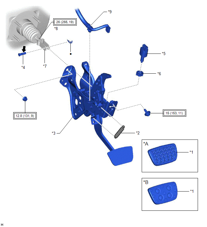
|
*A | w/ Rubber Pad |
*B | w/ Aluminum Pad |
|
*1 | BRAKE PEDAL PAD |
*2 | BRAKE PEDAL RETURN SPRING |
|
*3 | BRAKE PEDAL SUPPORT ASSEMBLY |
*4 | PUSH ROD PIN |
|
*5 | STOP LIGHT SWITCH ASSEMBLY |
*6 | STOP LIGHT SWITCH MOUNTING ADJUSTER |
|
*7 | BRAKE MASTER CYLINDER PUSH ROD CLEVIS |
*8 | LOCK NUT |
|
*9 | WIRE HARNESS |
- | - |
 |
Tightening torque for "Major areas involving basic vehicle performance such as moving/turning/stopping" : N*m (kgf*cm, ft.*lbf) |
â—Ź | Non-reusable part |
 |
Lithium soap base glycol grease |
- | - |
Installation
INSTALLATION
PROCEDURE
1. INSTALL BRAKE PEDAL PAD
(a) Install the brake pedal pad to the brake pedal support assembly.
HINT:
Installation is easier after applying a small amount of soapy water.
2. INSTALL STOP LIGHT SWITCH MOUNTING ADJUSTER
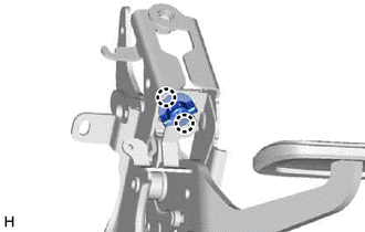
(a) Engage the 2 claws to install the stop light switch mounting adjuster.
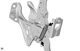
3. INSTALL BRAKE PEDAL RETURN SPRING
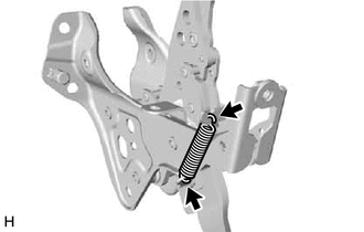
| (a) Install the brake pedal return spring to the brake pedal support assembly.
NOTICE: Attach
the bottom part of the brake pedal return spring first, making sure
that the open part of the hook is facing the front of the vehicle.
Attach the top part of the brake pedal return spring second, making sure
that the open part of the hook is facing the rear of the vehicle. |
|
4. INSTALL BRAKE PEDAL SUPPORT ASSEMBLY
(a)
Push the brake booster assembly toward the engine compartment, and
install the brake pedal support assembly while avoiding the stud bolts
of the brake booster assembly and brake booster support base.
NOTICE:
- Be careful not to deform the bracket of the instrument panel reinforcement assembly.
- Do not apply excessive force to the brake lines.
- Do not apply excessive force to the wire harness.
(b) Return the brake booster assembly to its original position.
(c) Install the brake pedal support assembly with the 4 nuts.
Torque:
12.8 N·m {131 kgf·cm, 9 ft·lbf}
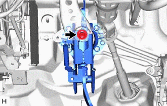
(d) Install the brake pedal support assembly to the instrument panel reinforcement assembly with the bolt.
Torque:
15 N·m {153 kgf·cm, 11 ft·lbf}
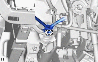
(e) Engage the clamp to install the wire harness to the brake pedal support assembly.
5. INSTALL PUSH ROD PIN
(a) Apply lithium soap base glycol grease to the push rod pin.
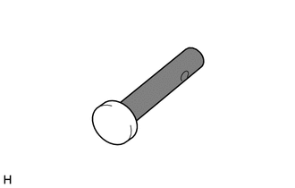
 | Lithium Soap Base Glycol Grease |
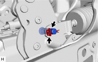
| (b)
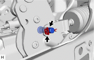
Connect the brake master cylinder push rod clevis to the brake pedal
support assembly with the push rod pin, and install a new clip as shown
in the illustration. HINT: The push rod pin can be installed in either direction. |
|
6. INSTALL STOP LIGHT SWITCH ASSEMBLY
Click here

7. INSTALL NO. 1 INSTRUMENT PANEL UNDER COVER SUB-ASSEMBLY
Click here 
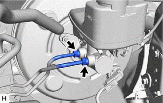
8. CONNECT BRAKE LINE
| (a) Using a union nut wrench, connect the 2 brake lines to the brake master cylinder sub-assembly.
Torque: Specified tightening torque : 19.5 N·m {199 kgf·cm, 14 ft·lbf}
NOTICE:
- Do not kink or damage the brake lines.
- Do not allow the brake lines to twist or interfere with other parts or the vehicle body during tightening.
- Do not allow any foreign matter such as dirt or dust to enter the brake lines from the connecting parts.
HINT:
|
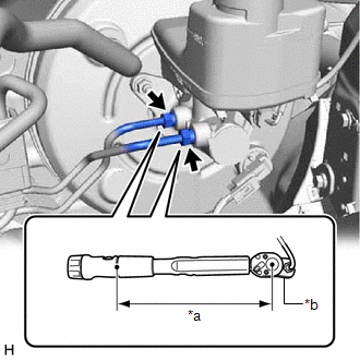 |
|
*a | Torque Wrench Fulcrum Length | |
*b | Union Nut Wrench | | |
9. BLEED BRAKE SYSTEM
Click here 
10. INSTALL BATTERY
Click here 
11. INSPECT AND ADJUST BRAKE PEDAL
Click here

Removal
REMOVAL
CAUTION / NOTICE / HINT
The
necessary procedures (adjustment, calibration, initialization or
registration) that must be performed after parts are removed and
installed, or replaced during brake pedal support assembly
removal/installation are shown below.
Necessary Procedures After Parts Removed/Installed/Replaced |
Replaced Part or Performed Procedure |
Necessary Procedure | Effect/Inoperative Function when Necessary Procedure not Performed |
Link |
|
*: When performing learning using the Techstream.
Click here  |
|
Battery terminal is disconnected/reconnected |
Perform steering sensor zero point calibration |
Lane departure alert system (w/ Steering Control) |
 |
|
Pre-collision system |
|
Intelligent Clearance Sonar System* |
|
Lighting System (for Gasoline Model with Cornering Light) |
|
Memorize steering angle neutral point |
Parking assist monitor system |
 |
|
Panoramic View Monitor System |
 |
PROCEDURE
1. PRECAUTION
NOTICE:
After
turning the engine switch off, waiting time may be required before
disconnecting the cable from the negative (-) battery terminal.
Therefore, make sure to read the disconnecting the cable from the
negative (-) battery terminal notices before proceeding with work.
Click here

2. REMOVE BATTERY
Click here

3. DRAIN BRAKE FLUID
NOTICE:
If brake fluid leaks onto any painted surface, immediately wash it off.
4. DISCONNECT BRAKE LINE
|
(a) Using a union nut wrench, disconnect the 2 brake lines from the brake master cylinder sub-assembly.
NOTICE:
- Do not damage or deform the brake lines.
- Do not allow any foreign matter such as dirt or dust to enter the brake lines from the connecting parts.
| |
5. REMOVE NO. 1 INSTRUMENT PANEL UNDER COVER SUB-ASSEMBLY
Click here

6. REMOVE STOP LIGHT SWITCH ASSEMBLY
Click here 
7. REMOVE PUSH ROD PIN
| (a) Remove the clip and push rod pin. | |
8. REMOVE BRAKE PEDAL SUPPORT ASSEMBLY
| (a) Disengage the clamp to separate the wire harness from the brake pedal support assembly. |
|
| (b) Remove the bolt and separate the brake pedal support assembly from the instrument panel reinforcement assembly. |
|
(c) Remove the 2 clips.
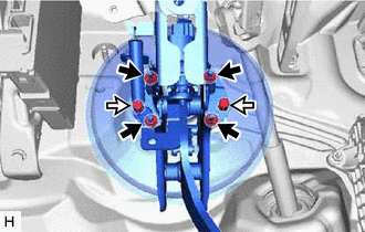
 |
Nut |
 |
Clip |
HINT:
Depending on the vehicle, the clips may not be installed.
(d) Remove the 4 nuts and push the brake booster assembly toward the engine compartment.
NOTICE:
- Do not apply excessive force to the brake lines.
- Do not apply excessive force to the wire harness.
(e) Remove the brake pedal support
assembly while avoiding the stud bolts of the brake booster assembly and
brake booster support base.
NOTICE:
Be careful not to deform the bracket of the instrument panel reinforcement assembly.
9. REMOVE BRAKE PEDAL RETURN SPRING
| (a) Remove the brake pedal return spring from the brake pedal support assembly. |
|
10. REMOVE STOP LIGHT SWITCH MOUNTING ADJUSTER
| (a) Disengage the 2 claws and remove the stop light switch mounting adjuster. |
|
11. REMOVE BRAKE PEDAL PAD
(a) Remove the brake pedal pad from the brake pedal support assembly.


