Brake Actuator Operation Sound is Loud during Initial Check
CAUTION / NOTICE / HINT
NOTICE:
When
replacing the skid control ECU (brake actuator assembly), perform
system variant learning and acceleration sensor zero point calibration.
Click here

PROCEDURE
(a)
After turning the engine switch on (IG), compare the operating sound of
the brake actuator the first time the vehicle speed reaches 45 km/h (28
mph) with a known good vehicle of the same model.
OK:
The operating sound is the same or quieter than that of a known good vehicle of the same model.
HINT:
When
the vehicle speed reaches approximately 40 km/h (25 mph), the initial
check of the brake actuator assembly is performed and pump motor
operation sounds are generated.
| OK |  |
END |
|
NG |
 | |
| 2. |
CHECK BRAKE ACTUATOR BOLT CUSHION |
(a) Check that the cushion of the brake actuator bracket assembly is not worn, damaged or deformed.
OK:
The brake actuator bracket assembly is not worn, damaged or deformed.
| NG |
 | REPLACE BRAKE ACTUATOR BOLT CUSHION |
|
OK |
 | |
| 3. |
ADJUST INSTALLATION OF BRAKE ACTUATOR ASSEMBLY |
(a) Drain the brake fluid.
(b) Disconnect all brake lines from the brake actuator assembly.
Click here 
(c) Connect each brake line so that the cushion of the brake actuator assembly is tensioned evenly.
Click here 
NOTICE:
After connecting all the brake lines, add brake fluid and bleed the brake system.
Click here 
HINT:
By reducing the tension on the brake lines and cushion, the operating sound of the brake actuator assembly may be reduced.
(d) Check that no brake lines interfere with the vehicle body or other components.
|
NEXT |
 | |
(a) Perform a road test and check the magnitude of the operating sound again.
OK:
The operating sound is the same or quieter than that of a known good vehicle of the same model.
| OK |
 | END |
| NG |
 | REPLACE BRAKE ACTUATOR ASSEMBLY |
Brake Hold Operated Indicator Light Circuit
DESCRIPTION
The brake hold
operated indicator light illuminates when the brake hold system is
operating (vehicle stopped due to brake fluid pressure hold) and turns
off when the brake hold system operation is finished (brake fluid
pressure decreases).
The brake hold system may
not operate depending on vehicle conditions even when the system is in
standby mode and the brake hold standby indicator light is illuminated.
If
there is a system malfunction that causes brake hold control to be
prohibited, when the vehicle is under the following conditions and the
brake hold switch (electric parking brake switch assembly) is pressed,
the brake hold operated indicator light blinks.
- Vehicle Conditions:
- The driver door is closed.
- The driver seat belt is fastened.
CAUTION / NOTICE / HINT
NOTICE:
When
replacing the skid control ECU (brake actuator assembly), perform
system variant learning and acceleration sensor zero point calibration.
Click here

PROCEDURE
(a) Check that the brake hold standby indicator light operates normally.
(b)
If the brake hold operated indicator light does not illuminate even
though the brake hold standby indicator light is illuminated, check that
the following brake hold operation (brake fluid pressure is being
maintained ) conditions are met.
- The shift lever is not in P or R.
- The vehicle is fully stopped and the driver is depressing the brake pedal.
- The driver is not depressing the accelerator pedal.
- The vehicle is not on a steep incline.
HINT:
When a malfunction occurs in the brake control system, the brake hold operated indicator light blinks.
|
NEXT |
 | |
| 2. |
INSPECT COMBINATION METER ASSEMBLY |
(a) Enter the following menus: Body Electrical / Combination Meter / Active Test.
(b) Perform the Active Test of the combination meter assembly using the Techstream.
Body Electrical > Combination Meter > Active Test
|
Tester Display |
| Hold Indicator |
(c) Check the combination meter assembly.
OK:
The brake hold operated indicator light turns on or off in accordance with the Techstream operation.
| NG |
 | INSPECT METER / GAUGE SYSTEM |
|
OK |
 | |
| 3. |
PERFORM ACTIVE TEST USING TECHSTREAM (BRAKE HOLD OPERATED INDICATOR LIGHT) |
(a) Enter the following menus: Chassis / ABS/VSC/TRAC/EPB / Active Test.
Chassis > ABS/VSC/TRAC/EPB > Active Test
|
Tester Display | Measurement Item |
Control Range | Diagnostic Note |
|
BH Operated Light | Brake hold operated indicator light |
Indicator light OFF/ON |
- Observe combination meter assembly
- Perform the Active Test with the vehicle stopped
|
Chassis > ABS/VSC/TRAC/EPB > Data List
|
Tester Display | Measurement Item |
Range | Normal Condition |
Diagnostic Note |
|
BH Operated Light | Brake hold operated indicator light |
ON or OFF | ON: Indicator light on
OFF: Indicator light off |
- |
Chassis > ABS/VSC/TRAC/EPB > Active Test
|
Active Test Display |
|
BH Operated Light |
|
Data List Display |
|
BH Operated Light |
(b) Check the operating condition of the brake hold operated indicator light when operating it using the Techstream.
| Result |
Proceed to |
| Brake hold operated indicator light in the Data List does not change using the Active Test. |
A |
| Brake hold operated indicator light in the Data List turns ON/OFF using the Active Test. |
B |
| A |
 | REPLACE BRAKE ACTUATOR ASSEMBLY |
| B |
 | USE SIMULATION METHOD TO CHECK |
Brake Hold Standby Indicator Light Circuit
DESCRIPTION
The brake hold
standby indicator light turns on if brake hold control is possible when
the following conditions required for operation standby are met and the
brake hold switch (electric parking brake switch assembly) is pressed
while the engine switch is on (IG).
- Conditions required for operation standby:
- The driver door is closed.
- The driver seat belt is fastened.
- The system is normal.
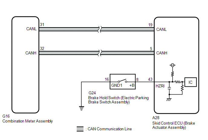
WIRING DIAGRAM

CAUTION / NOTICE / HINT
NOTICE:
When
replacing the skid control ECU (brake actuator assembly), perform
system variant learning and acceleration sensor zero point calibration.
Click here

PROCEDURE
(a)
If the brake hold standby indicator light does not illuminate even
though the brake hold switch (electric parking brake switch assembly) is
pushed, check that the brake hold function operation conditions are
met.
- The driver door is closed.
- The driver seat belt is fastened.
- The system is normal.
|
NEXT |
 | |
| 2. |
CHECK CAN COMMUNICATION SYSTEM |
(a) Check if CAN communication system DTCs are output.
Click here 
|
Result | Proceed to |
|
DTCs are not output | A |
|
DTCs are output | B |
| B |
 | CHECK CAN COMMUNICATION SYSTEM |
|
A |
 | |
| 3. |
CHECK IF BRAKE ACTUATOR ASSEMBLY CONNECTOR IS SECURELY CONNECTED |
(a) Check if the skid control ECU (brake actuator assembly) connector is securely connected.
OK:
The connector is securely connected.
| NG |
 | CONNECT CONNECTOR TO BRAKE ACTUATOR ASSEMBLY CORRECTLY |
|
OK |
 | |
| 4. |
INSPECT COMBINATION METER ASSEMBLY |
(a) Turn the engine switch off.
(b) Enter the following menus: Body Electrical / Combination Meter / Active Test.
(c) Perform the Active Test of the combination meter assembly using the Techstream.
Body Electrical > Combination Meter > Active Test
|
Tester Display |
| Brake Hold Indicator |
(d) Check the combination meter assembly.
OK:
The brake hold standby indicator light turns on or off in accordance with the Techstream operation.
| NG |
 | INSPECT METER / GAUGE SYSTEM |
|
OK |
 | |
| 5. |
PERFORM ACTIVE TEST USING TECHSTREAM (BRAKE HOLD STANDBY INDICATOR LIGHT) |
(a) Enter the following menus: Chassis / ABS/VSC/TRAC/EPB / Active Test.
Chassis > ABS/VSC/TRAC/EPB > Active Test
|
Tester Display | Measurement Item |
Control Range | Diagnostic Note |
|
BH Standby Light | Brake hold standby indicator light |
Indicator light OFF/ON |
Observe combination meter assembly Vehicle condition: Vehicle stopped |
Chassis > ABS/VSC/TRAC/EPB > Data List
|
Tester Display | Measurement Item |
Range | Normal Condition |
Diagnostic Note |
|
BH Standby Light | Brake hold standby indicator light |
ON or OFF | ON: Indicator light on
OFF: Indicator light off |
- |
Chassis > ABS/VSC/TRAC/EPB > Active Test
|
Active Test Display |
|
BH Standby Light |
|
Data List Display |
|
BH Standby Light |
(b) Check the operating condition of the brake hold standby indicator light when operating it using the Techstream.
| Result |
Proceed to |
| Brake hold standby indicator light in the Data List does not change using the Active Test. |
A |
| Brake hold standby indicator light in the Data List turns ON/OFF using the Active Test. |
B |
| A |
 | REPLACE BRAKE ACTUATOR ASSEMBLY |
|
B |
 | |
| 6. |
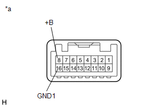
INSPECT ELECTRIC PARKING BRAKE SWITCH ASSEMBLY |
| (a) Turn the engine switch off. |
 |
|
*a | Component without harness connected
(Brake Hold Switch (Electric Parking Brake Switch Assembly)) | | |
(b) Make sure that there is no looseness at the locking part and the connecting part of the connector.
OK:
The connector is securely connected.
(c) Disconnect the G24 brake hold switch (electric parking brake switch assembly) connector.
(d) Check both the connector case and the terminal for deformation and corrosion.
OK:
No deformation or corrosion.
(e) Measure the resistance according to the value(s) in the table below.
Standard Resistance:
|
Tester Connection | Condition |
Specified Condition |
|
8 (+B) - 16 (GND1) | Switch pushed |
Below 1 Ω |
|
8 (+B) - 16 (GND1) | Switch not pushed |
10 kΩ or higher |
| NG |
 | REPLACE ELECTRIC PARKING BRAKE SWITCH ASSEMBLY |
|
OK |
 | |
| 7. |
CHECK HARNESS AND CONNECTOR (BRAKE ACTUATOR ASSEMBLY - ELECTRIC PARKING BRAKE SWITCH ASSEMBLY) |
(a) Make sure that there is no looseness at the locking part and the connecting part of the connector.
OK:
The connector is securely connected.
(b) Disconnect the A28 skid control ECU (brake actuator assembly) connector.
(c) Check both the connector case and the terminal for deformation and corrosion.
OK:
No deformation or corrosion.
(d) Measure the resistance according to the value(s) in the table below.
Standard Resistance:
|
Tester Connection | Condition |
Specified Condition |
|
A28-43 (HZRI) - G24-8 (+B) |
Always | Below 1 Ω |
|
A28-43 (HZRI) or G24-8 (+B) - Body ground |
Always | 10 kΩ or higher |
|
G24-16 (GND1) - Body ground |
Always | Below 1 Ω |
| OK |
 | REPLACE BRAKE ACTUATOR ASSEMBLY |
| NG |
 | REPAIR OR REPLACE HARNESS OR CONNECTOR |


