ABS Operates Before Necessary When Braking
DESCRIPTION
Troubleshooting for when ABS operates too soon due to a noisy signal from the speed sensor, a difference in output, etc.
PROCEDURE
| 1. |
PERFORM TEST MODE (SIGNAL CHECK) INSPECTION (SPEED SENSOR CIRCUIT) |
(a) Enter the following menus: Chassis / ABS/VSC/TRAC/EPB / Utility / Signal Check.
(b)
Using the Techstream, perform a Test Mode (Signal Check) inspection
sensor check and check that speed sensor Test Mode (Signal Check)
inspection items change from incomplete to complete.
Click here

Chassis > ABS/VSC/TRAC/EPB > Utility
|
Tester Display |
| Signal Check |
OK:
Speed sensor Test Mode (Signal Check) inspection items change from incomplete to complete.
|
Result | Proceed to |
|
OK (for Front) | A |
|
OK (for Rear) | B |
|
NG | C |
NOTICE:
- When cleaning the front speed sensor, make sure to clean the installation hole before installation.
- Do not use parts cleaner when cleaning the front speed sensor rotor.
HINT:
The rear speed sensor and rear speed sensor rotor are incorporated into the rear axle hub and bearing assembly.
If the rear speed sensor and rear speed sensor rotor need to be replaced, replace the rear axle hub and bearing assembly.
| A |
 | CLEAN FRONT SPEED SENSOR AND FRONT SPEED SENSOR ROTOR |
| B |
 | REPLACE REAR AXLE HUB AND BEARING ASSEMBLY |
| C |
 | INSPECT AND REPAIR MALFUNCTIONING SPEED SENSOR CIRCUIT |
ABS Warning Light does not Come ON
DESCRIPTION
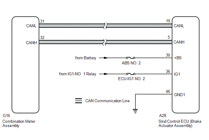
The skid control ECU (brake actuator assembly) is connected to the combination meter assembly via CAN communication.
CAUTION / NOTICE / HINT
NOTICE:
When
replacing the skid control ECU (brake actuator assembly), perform
system variant learning and acceleration sensor zero point calibration.
Click here

PROCEDURE
| 1. |
CHECK CAN COMMUNICATION SYSTEM |
(a) Check if CAN communication system DTCs are output.
Click here 
|
Result | Proceed to |
|
DTCs are not output | A |
|
DTCs are output | B |
| B |
 | INSPECT CAN COMMUNICATION SYSTEM |
|
A |
 | |
| 2. |
PERFORM ACTIVE TEST USING TECHSTREAM (ABS WARNING LIGHT) |
(a) Enter the following menus: Chassis / ABS/VSC/TRAC/EPB / Active Test.
Chassis > ABS/VSC/TRAC/EPB > Active Test
|
Tester Display | Measurement Item |
Control Range | Diagnostic Note |
|
ABS Warning Light | ABS warning light |
Warning light OFF/ON | Observe combination meter assembly |
Chassis > ABS/VSC/TRAC/EPB > Data List
|
Tester Display | Measurement Item |
Range | Normal Condition |
Diagnostic Note |
|
ABS Warning Light | ABS warning light |
ON or OFF | ON: Warning light on
OFF: Warning light off |
- |
Chassis > ABS/VSC/TRAC/EPB > Active Test
|
Active Test Display |
|
ABS Warning Light |
|
Data List Display |
|
ABS Warning Light |
(b) Check the operating condition of the ABS warning light when operating it using the Techstream.
| Result |
Proceed to |
| ABS warning light in the Data List does not change using the Active Test |
A |
| ABS warning light in the Data List turns ON/OFF using the Active Test |
B |
| A |
 | REPLACE BRAKE ACTUATOR ASSEMBLY |
|
B |
 | |
| 3. |
INSPECT COMBINATION METER ASSEMBLY |
(a) Enter the following menus: Body Electrical / Combination Meter / Active Test.
(b) Perform the Active Test of the combination meter assembly using the Techstream.
Body Electrical > Combination Meter > Active Test
|
Tester Display |
| ABS Warning |
(c) Check the combination meter assembly.
OK:
The ABS warning light turns on or off in accordance with Techstream operation.
| OK |
 | REPLACE BRAKE ACTUATOR ASSEMBLY |
| NG |
 | INSPECT METER / GAUGE SYSTEM |
ABS Warning Light Remains ON
DESCRIPTION
The skid
control ECU (brake actuator assembly) is connected to the combination
meter assembly via CAN communication. If any of the following is
detected, the ABS warning light remains on:
- The skid control ECU (brake actuator assembly) connector is disconnected from the skid control ECU (brake actuator assembly).
- There is a malfunction in the skid control ECU (brake actuator assembly) internal circuit.
- There is an open in the harness between the combination meter and skid control ECU (brake actuator assembly).
- The ABS is defective.
HINT:
In some cases, the Techstream cannot be used when the skid control ECU (brake actuator assembly) is abnormal.
WIRING DIAGRAM

CAUTION / NOTICE / HINT
NOTICE:
- When replacing the skid control ECU (brake actuator assembly), perform
system variant learning and acceleration sensor zero point calibration.
Click here 
- Inspect the fuses for circuits related to this system before performing the following procedure.
- Before performing this procedure, depress the brake pedal and confirm that the stop lights illuminate.
PROCEDURE
|
1. | CHECK CAN COMMUNICATION SYSTEM |
(a) Check if CAN communication system DTCs are output.
Click here

|
Result | Proceed to |
|
DTCs are not output | A |
|
DTCs are output | B |
| B |
 | INSPECT CAN COMMUNICATION SYSTEM |
|
A |
 | |
| 2. |
CHECK IF BRAKE ACTUATOR ASSEMBLY CONNECTOR IS SECURELY CONNECTED |
(a) Check if the skid control ECU (brake actuator assembly) connector is securely connected.
OK:
The connector is securely connected.
| NG |
 | CONNECT CONNECTOR TO BRAKE ACTUATOR ASSEMBLY CORRECTLY |
|
OK |
 | |
(a) Check the battery voltage.
Standard Voltage:
|
Tester Connection | Condition |
Specified Condition |
|
Positive (+) terminal - Negative (-) terminal |
Engine switch off | 11 to 14 V |
| NG |
 | CHECK OR REPLACE CHARGING SYSTEM COMPONENT OR BATTERY |
|
OK |
 | |
| 4. |
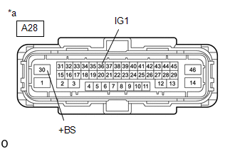
CHECK HARNESS AND CONNECTOR (POWER SOURCE TERMINAL) |
| (a) Turn the engine switch off. |
 |
|
*a | Front view of wire harness connector
(to Skid Control ECU (Brake Actuator Assembly)) | | |
(b) Make sure that there is no looseness at the locking part and the connecting part of the connector.
OK:
The connector is securely connected.
(c) Disconnect the A28 skid control ECU (brake actuator assembly) connector.
(d) Check both the connector case and the terminals for deformation and corrosion.
OK:
No deformation or corrosion.
(e) Measure the voltage according to the value(s) in the table below.
Standard Voltage:
|
Tester Connection | Condition |
Specified Condition |
|
A28-30 (+BS) - Body ground |
Always | 11 to 14 V |
|
A28-36 (IG1) - Body ground |
Engine switch on (IG) |
11 to 14 V |
| NG |
 | REPAIR OR REPLACE HARNESS OR CONNECTOR (POWER SOURCE CIRCUIT) |
|
OK |
 | |
| 5. |
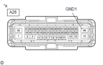
CHECK HARNESS AND CONNECTOR (GND1 TERMINAL) |
| (a) Turn the engine switch off. |
 |
|
*a | Front view of wire harness connector
(to Skid Control ECU (Brake Actuator Assembly)) | | |
(b) Measure the resistance according to the value(s) in the table below.
Standard Resistance:
|
Tester Connection | Condition |
Specified Condition |
|
A28-46 (GND1) - Body ground |
Always | Below 1 О© |
| NG |
 | REPAIR OR REPLACE HARNESS OR CONNECTOR (GND1 CIRCUIT) |
|
OK |
 | |
| 6. |
READ VALUE USING TECHSTREAM (ABS WARNING LIGHT) |
(a) Reconnect the A28 skid control ECU (brake actuator assembly) connector.
(b) Enter the following menus: Chassis / ABS/VSC/TRAC/EPB / Data List.
Chassis > ABS/VSC/TRAC/EPB > Data List
|
Tester Display | Measurement Item |
Range | Normal Condition |
Diagnostic Note |
|
ABS Warning Light | ABS warning light |
ON or OFF | ON: Warning light on
OFF: Warning light off |
- |
Chassis > ABS/VSC/TRAC/EPB > Data List
|
Tester Display |
| ABS Warning Light |
(c) Check the Techstream display condition of the ABS warning light.
| Result |
Proceed to |
| The value of ABS Warning Light is ON |
A |
| The value of ABS Warning Light is OFF |
B |
| A |
 | REPLACE BRAKE ACTUATOR ASSEMBLY |
| B |
 | INSPECT METER / GAUGE SYSTEM |


