Toyota Avalon (XX50): Electric Parking Brake System(for Gasoline Model)
Electric Current of Motor (C13A5,C13B0)
DESCRIPTION
The following DTCs are stored when a malfunction occurs in the skid control ECU (brake actuator assembly).
|
DTC No. | Detection Item |
DTC Detection Condition | Trouble Area |
Memory | Note |
|
C13A5 | Electric Current of Motor |
An electric parking brake motor failure. |
Skid control ECU (brake actuator assembly) |
DTC stored | An electric parking brake system malfunction is displayed on the multi-information display. |
|
C13B0 | Electric Parking Brake ECU Malfunction |
An electric parking brake ECU malfunction. |
Skid control ECU (brake actuator assembly) |
DTC stored | An electric parking brake system malfunction is displayed on the multi-information display. |
CAUTION / NOTICE / HINT
NOTICE:
When
replacing the skid control ECU (brake actuator assembly), operate the
electric parking brake switch (electric parking brake switch assembly)
as the parking brake indicator light (red) blinks when the engine switch
is first turned on (IG).
PROCEDURE
| 1. |
REPLACE SKID CONTROL ECU (BRAKE ACTUATOR ASSEMBLY) |
(a) Replace the skid control ECU (brake actuator assembly).
Click here

| NEXT |  |
END |
Open or Short Circuit in Motor (C13A6)
DESCRIPTION
|
DTC No. | Detection Item |
DTC Detection Condition | Trouble Area |
Memory | Note |
|
C13A6 | Open or Short Circuit in Motor |
Parking brake actuator assembly open or short circuit is detected for 0.015 seconds or more. |
- Parking brake actuator assembly
- Wire harness or connector
- Skid control ECU (brake actuator assembly)
| DTC stored |
An electric parking brake system malfunction is displayed on the multi-information display. |
WIRING DIAGRAM
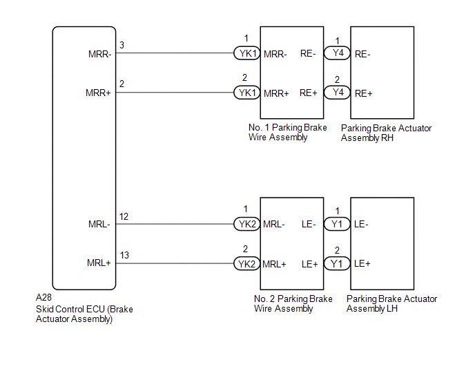
CAUTION / NOTICE / HINT
NOTICE:
- The electric parking brake may still operate up to 20 seconds after the
engine switch is turned off. Before disconnecting connectors or fuses,
turn the engine switch off and wait 20 seconds or more.
- When replacing the skid control ECU (brake actuator assembly), operate
the electric parking brake switch (electric parking brake switch
assembly) as the parking brake indicator light blinks (red) when the
engine switch is first turned on (IG).
PROCEDURE
|
1. | READ VALUE USING TECHSTREAM (PERMISSION OF RH INTERLOCKING PKB LOCK / PERMISSION OF LH INTERLOCKING PKB LOCK) |
(a) Turn the engine switch off.
(b) Connect the Techstream to the DLC3.
(c) Turn the engine switch on (IG).
(d) Turn the Techstream on.
(e) Enter the following menus: Chassis / ABS/VSC/TRAC/EPB / Data List.
(f) Read the Data List according to the display on the Techstream.
Chassis > ABS/VSC/TRAC/EPB > Data List
|
Tester Display | Measurement Item |
Range | Normal Condition |
Diagnostic Note |
|
Permission of RH Interlocking PKB Lock |
Parking brake actuator assembly RH parking brake lock control permission status |
OK or NG | OK |
- |
| Permission of LH Interlocking PKB Lock |
Parking brake actuator assembly LH parking brake lock control permission status |
OK or NG | OK |
- |
Chassis > ABS/VSC/TRAC/EPB > Data List
|
Tester Display |
| Permission of RH Interlocking PKB Lock |
|
Permission of LH Interlocking PKB Lock |
|
NEXT |
 | |
| 2. |
INSPECT PARKING BRAKE WIRE ASSEMBLY |
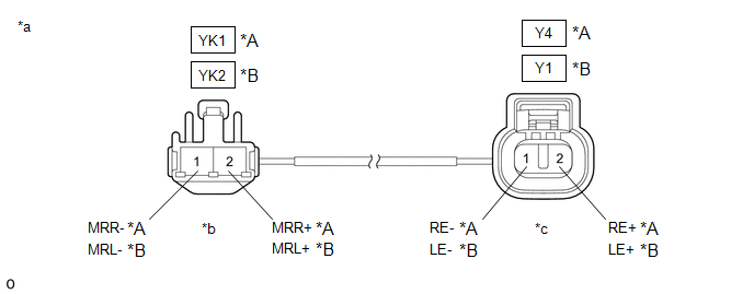
|
*A | RH |
*B | LH |
|
*a | Front view of Parking Brake Wire Assembly |
*b | (to wire harness connector) |
|
*c | (to Parking Brake Actuator Assembly) |
- | - |
(a) Turn the engine switch off.
(b) Make sure that there is no looseness at the locking part and the connecting part of the connectors.
OK:
The connector is securely connected.
(c) Remove the parking brake wire assembly.
(d) Check both the connector case and the terminals for deformation and corrosion.
OK:
No deformation or corrosion.
(e) Inspect the parking brake wire assembly.
Standard Resistance:
RH |
Tester Connection | Condition |
Specified Condition |
|
YK1-1 (MRR-) - Y4-1 (RE-) |
Always | Below 1 Ω |
|
YK1-1 (MRR-) or Y4-1 (RE-) - Body ground and other terminals |
Always | 10 kΩ or higher |
|
YK1-2 (MRR+) - Y4-2 (RE+) |
Always | Below 1 Ω |
|
YK1-2 (MRR+) or Y4-2 (RE+) - Body ground and other terminals |
Always | 10 kΩ or higher |
LH |
Tester Connection | Condition |
Specified Condition |
|
YK2-1 (MRL-) - Y1-1 (LE-) |
Always | Below 1 Ω |
|
YK2-1 (MRL-) or Y1-1 (LE-) - Body ground and other terminals |
Always | 10 kΩ or higher |
|
YK2-2 (MRL+) - Y1-2 (LE+) |
Always | Below 1 Ω |
|
YK2-2 (MRL+) or Y1-2 (LE+) - Body ground and other terminals |
Always | 10 kΩ or higher |
| NG |
 | REPLACE PARKING BRAKE WIRE ASSEMBLY |
|
OK |
 | |
| 3. |
CHECK HARNESS AND CONNECTOR (SKID CONTROL ECU (BRAKE ACTUATOR ASSEMBLY) - PARKING BRAKE ACTUATOR ASSEMBLY) |
(a) Turn the engine switch off.
(b) Make sure the parking brake wire assembly is securely installed.
(c) Disconnect the A28 skid control ECU (brake actuator assembly) connector.
(d) Disconnect the Y4 or Y1 parking brake actuator assembly connector.
(e) Measure the resistance according to the value(s) in the table below.
Standard Resistance:
RH |
Tester Connection | Condition |
Specified Condition |
|
A28-2 (MRR+) - Y4-2 (RE+) |
Always | Below 1 Ω |
|
A28-3 (MRR-) - Y4-1 (RE-) |
Always | Below 1 Ω |
|
A28-2 (MRR+) or Y4-2 (RE+) - Body ground |
Always | 10 kΩ or higher |
|
A28-2 (MRR+) or Y4-1 (RE-) - Body ground |
Always | 10 kΩ or higher |
LH |
Tester Connection | Condition |
Specified Condition |
|
A28-13 (MRL+) - Y1-2 (LE+) |
Always | Below 1 Ω |
|
A28-12 (MRL-) - Y1-1 (LE-) |
Always | Below 1 Ω |
|
A28-13 (MRL+) or Y1-2 (LE+) - Body ground |
Always | 10 kΩ or higher |
|
A28-12 (MRL-) or Y1-1 (LE-) - Body ground |
Always | 10 kΩ or higher |
| NG |
 | REPAIR OR REPLACE HARNESS OR CONNECTOR |
|
OK |
 | |
| 4. |
INSPECT PARKING BRAKE ACTUATOR ASSEMBLY |
(a) Remove the parking brake actuator assembly.
Click here

(b) Inspect the parking brake actuator assembly.
Click here 
| OK |
 | REPLACE SKID CONTROL ECU (BRAKE ACTUATOR ASSEMBLY) |
| NG |
 | REPLACE PARKING BRAKE ACTUATOR ASSEMBLY |
Actuator Malfunction (C13A7)
DESCRIPTION
|
DTC No. | Detection Item |
DTC Detection Condition | Trouble Area |
Memory | Note |
|
C13A7 | Actuator Malfunction |
When the electric parking brake is operating, motor lock, gear lock, motor spinning or repeated slipping occurs. |
- Parking brake actuator assembly
- Rear brake
- Wire harness or connector
| DTC stored |
An electric parking brake system malfunction is displayed on the multi-information display. |
WIRING DIAGRAM
Click here 
CAUTION / NOTICE / HINT
NOTICE:
- This DTC may be stored when the system changes to pad replacement mode, but this is not a malfunction.
- This DTC may be stored when the parking brake is forcibly released, but this is not a malfunction.
- The electric parking brake may still operate up to 20 seconds after the
engine switch is turned off. Before disconnecting connectors or fuses,
turn the engine switch off and wait 20 seconds or more.
- When replacing the skid control ECU (brake actuator assembly), operate
the electric parking brake switch (electric parking brake switch
assembly) as the parking brake indicator light (red) blinks when the
engine switch is first turned on (IG).
PROCEDURE
(a) Check for DTCs.
Chassis > ABS/VSC/TRAC/EPB > Trouble Codes
|
Result | Proceed to |
|
Only DTC C13A7 is output |
A |
| DTCs other than C13A7 are output |
B |
| B |
 | GO TO DIAGNOSTIC TROUBLE CODE CHART |
|
A |
 | |
| 2. |
READ VALUE USING TECHSTREAM (PERMISSION OF RH INTERLOCKING PKB LOCK / PERMISSION OF LH INTERLOCKING PKB LOCK) |
(a) Turn the engine switch off.
(b) Connect the Techstream to the DLC3.
(c) Turn the engine switch on (IG).
(d) Turn the Techstream on.
(e) Enter the following menus: Chassis / ABS/VSC/TRAC/EPB / Data List.
(f) Read the Data List according to the display on the Techstream.
Chassis > ABS/VSC/TRAC/EPB > Data List
|
Tester Display | Measurement Item |
Range | Normal Condition |
Diagnostic Note |
|
Permission of RH Interlocking PKB Lock |
Parking brake actuator assembly RH parking brake lock control permission status |
OK or NG | OK |
- |
| Permission of LH Interlocking PKB Lock |
Parking brake actuator assembly LH parking brake lock control permission status |
OK or NG | OK |
- |
Chassis > ABS/VSC/TRAC/EPB > Data List
|
Tester Display |
| Permission of RH Interlocking PKB Lock |
|
Permission of LH Interlocking PKB Lock |
|
NEXT |
 | |
| 3. |
INSPECT PARKING BRAKE WIRE ASSEMBLY |
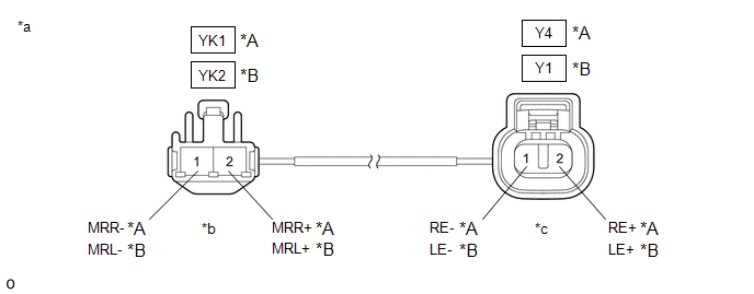
|
*A | RH |
*B | LH |
|
*a | Front view of Parking Brake Wire Assembly |
*b | (to wire harness connector) |
|
*c | (to Parking Brake Actuator Assembly) |
- | - |
(a) Turn the engine switch off.
(b) Make sure that there is no looseness at the locking part and the connecting part of the connectors.
OK:
The connector is securely connected.
(c) Remove the parking brake wire assembly.
(d) Check both the connector case and the terminals for deformation and corrosion.
OK:
No deformation or corrosion.
(e) Inspect the parking brake wire assembly.
Standard Resistance:
RH |
Tester Connection | Condition |
Specified Condition |
|
YK1-1 (MRR-) - Y4-1 (RE-) |
Always | Below 1 Ω |
|
YK1-1 (MRR-) or Y4-1 (RE-) - Body ground and other terminals |
Always | 10 kΩ or higher |
|
YK1-2 (MRR+) - Y4-2 (RE+) |
Always | Below 1 Ω |
|
YK1-2 (MRR+) or Y4-2 (RE+) - Body ground and other terminals |
Always | 10 kΩ or higher |
LH |
Tester Connection | Condition |
Specified Condition |
|
YK2-1 (MRL-) - Y1-1 (LE-) |
Always | Below 1 Ω |
|
YK2-1 (MRL-) or Y1-1 (LE-) - Body ground and other terminals |
Always | 10 kΩ or higher |
|
YK2-2 (MRL+) - Y1-2 (LE+) |
Always | Below 1 Ω |
|
YK2-2 (MRL+) or Y1-2 (LE+) - Body ground and other terminals |
Always | 10 kΩ or higher |
| NG |
 | REPLACE PARKING BRAKE WIRE ASSEMBLY |
|
OK |
 | |
| 4. |
CHECK HARNESS AND CONNECTOR (SKID CONTROL ECU (BRAKE ACTUATOR ASSEMBLY) - PARKING BRAKE ACTUATOR ASSEMBLY) |
(a) Turn the engine switch off.
(b) Make sure the parking brake wire assembly is securely installed.
(c) Disconnect the A28 skid control ECU (brake actuator assembly) connector.
(d) Disconnect the Y4 or Y1 parking brake actuator assembly connector.
(e) Measure the resistance according to the value(s) in the table below.
Standard Resistance:
RH |
Tester Connection | Condition |
Specified Condition |
|
A28-2 (MRR+) - Y4-2 (RE+) |
Always | Below 1 Ω |
|
A28-3 (MRR-) - Y4-1 (RE-) |
Always | Below 1 Ω |
|
A28-2 (MRR+) or Y4-2 (RE+) - Body ground |
Always | 10 kΩ or higher |
|
A28-2 (MRR+) or Y4-1 (RE-) - Body ground |
Always | 10 kΩ or higher |
LH |
Tester Connection | Condition |
Specified Condition |
|
A28-13 (MRL+) - Y1-2 (LE+) |
Always | Below 1 Ω |
|
A28-12 (MRL-) - Y1-1 (LE-) |
Always | Below 1 Ω |
|
A28-13 (MRL+) or Y1-2 (LE+) - Body ground |
Always | 10 kΩ or higher |
|
A28-12 (MRL-) or Y1-1 (LE-) - Body ground |
Always | 10 kΩ or higher |
| NG |
 | REPAIR OR REPLACE HARNESS OR CONNECTOR |
|
OK |
 | |
| 5. |
INSPECT REAR BRAKE AND PARKING BRAKE ACTUATOR ASSEMBLY |
(a) Enter rear brake pad replacement mode.
Click here

(b) Turn the engine switch off.
(c) Check that the rotating parts are not seized or the actuator is not spinning freely.
(1)
Check that the parking brake actuator assembly is installed properly to
the rear brake caliper and that it is not spinning freely.
For the parking brake actuator assembly removal procedure: Click here

(2) Check that there is no damage to the rotating parts from the parking brake actuator assembly to the rear brake caliper.
(3) Inspect the parking brake actuator assembly and check that it operates correctly.
Click here 
(4) Check that the rear brake caliper threaded part rotates and that the rear disc brake piston moves outward.
HINT:
For the check procedures, refer to the parking brake forced release method when not using the Techstream.
Click here 
HINT:
Return to normal mode after work is complete.
Click here 
| OK |
 | REPLACE PARKING BRAKE ACTUATOR ASSEMBLY |
| NG |
 | REPAIR OR REPLACE NECESSARY PARTS |
EPB High Temperature (C13AA)
DESCRIPTION
If the electric
parking brake is used continuously, system operation is stopped to
prevent the parking brake actuator assembly from overheating.
This
DTC is stored when system operation is stopped to prevent the parking
brake actuator assembly from overheating and is not a malfunction.
|
DTC No. | Detection Item |
DTC Detection Condition | Trouble Area |
Memory | Note |
|
C13AA | EPB High Temperature |
Protects the electric parking brake from overheating by frequently requested lock/release commands. |
Overheat due to continuous use of system |
DTC stored | A
warning is displayed on the multi-information display indicating
electric parking brake system operation is stopped due to high
temperatures. |
PROCEDURE
| 1. |
ELECTRIC PARKING BRAKE OVERHEAT |
(a) With the overheat warning displayed on the multi-information display, wait for approximately 1 minute.
(b) Check that the overheat warning has disappeared.
HINT:
- Check the display after turning the engine switch off and on (IG).
- After the warning has disappeared and the electric parking brake system returns to normal, clear the DTCs.
Chassis > ABS/VSC/TRAC/EPB > Clear DTCs
| NEXT |
 | END |
EPB Switch Malfunction (C13B4)
DESCRIPTION
When the
electric parking brake switch is pulled, a lock request signal is sent
from the skid control ECU (brake actuator assembly) to the parking brake
actuator assembly. When the electric parking brake switch is pushed, a
release request signal is sent from the skid control ECU (brake actuator
assembly) to the parking brake actuator assembly.
|
DTC No. | Detection Item |
DTC Detection Condition | Trouble Area |
Memory | Note |
|
C13B4 | EPB Switch Malfunction |
- Parking brake switch open or short circuit is detected for 1 second or more
- Parking brake switch stuck malfunction
|
- Electric parking brake switch (electric parking brake switch assembly)
- Wire harness or connector
- Skid control ECU (brake actuator assembly)
| DTC stored |
An electric parking brake system malfunction is displayed on the multi-information display. |
DTC Detection Conditions | |
Vehicle Condition |
|
Pattern 1 | Pattern 2 |
|
Diagnosis Condition | - |
- | - |
|
Malfunction Status | Parking brake switch open or short circuit is detected for 1 second or more |
â—‹ | - |
|
Parking brake switch stuck malfunction |
- | â—‹ |
|
Detection Time | 1 second or more |
- |
|
Number of Trips | 1 trip |
1 trip |
WIRING DIAGRAM
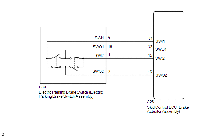
CAUTION / NOTICE / HINT
NOTICE:
- The electric parking brake may still operate up to 20 seconds after the
engine switch is turned off. Before disconnecting connectors or fuses,
turn the engine switch off and wait 20 seconds or more.
- When replacing the skid control ECU (brake actuator assembly), operate
the electric parking brake switch (electric parking brake switch
assembly) as the parking brake indicator light (red) blinks when the
engine switch is first turned on (IG).
PROCEDURE
|
1. | INSPECT ELECTRIC PARKING BRAKE SWITCH (ELECTRIC PARKING BRAKE SWITCH ASSEMBLY) |
(a) Remove the electric parking brake switch (electric parking brake switch assembly).
Click here 
(b) Inspect the electric parking brake switch (electric parking brake switch assembly).
Click here 
| NG |
 | REPLACE ELECTRIC PARKING BRAKE SWITCH (ELECTRIC PARKING BRAKE SWITCH ASSEMBLY) |
|
OK |
 | |
| 2. |
CHECK
HARNESS AND CONNECTOR (SKID CONTROL ECU (BRAKE ACTUATOR ASSEMBLY) -
ELECTRIC PARKING BRAKE SWITCH (ELECTRIC PARKING BRAKE SWITCH ASSEMBLY)) |
(a) Disconnect the G24 electric parking brake switch (electric parking brake switch assembly) connector.
(b) Disconnect the A28 skid control ECU (brake actuator assembly) connector.
(c) Measure the resistance according to the value(s) in the table below.
Standard Resistance:
|
Tester Connection | Condition |
Specified Condition |
|
A28-31 (SWI1) - G24-9 (SWI1) |
Always | Below 1 Ω |
|
A28-32 (SWO1) - G24-10 (SWO1) |
Always | Below 1 Ω |
|
A28-15 (SWI2) - G24-1 (SWI2) |
Always | Below 1 Ω |
|
A28-16 (SWO2) - G24-2 (SWO2) |
Always | Below 1 Ω |
|
A28-31 (SWI1) or G24-9 (SWI1) - Body ground |
Always | 10 kΩ or higher |
|
A28-32 (SWO1) or G24-10 (SWO1) - Body ground |
Always | 10 kΩ or higher |
|
A28-15 (SWI2) or G24-1 (SWI2) - Body ground |
Always | 10 kΩ or higher |
|
A28-16 (SWO2) or G24-2 (SWO2) - Body ground |
Always | 10 kΩ or higher |
| NG |
 | REPAIR OR REPLACE HARNESS OR CONNECTOR |
|
OK |
 | |
(a) Clear the DTCs.
Chassis > ABS/VSC/TRAC/EPB > Clear DTCs
(b) Turn the engine switch off.
(c) Turn the engine switch on (IG).
(d) Check for DTCs.
Chassis > ABS/VSC/TRAC/EPB > Trouble Codes
| Result |
Proceed to |
| DTCs are output |
A |
| DTCs are not output |
B |
| A |
 | REPLACE SKID CONTROL ECU (BRAKE ACTUATOR ASSEMBLY) |
| B |
 | USE SIMULATION METHOD TO CHECK |
Data List / Active Test
DATA LIST / ACTIVE TEST
READ DATA LIST
HINT:
Using
the Techstream to read the Data List allows the values or states of
switches, sensors, actuators and other items to be read without removing
any parts. This non-intrusive inspection can be very useful because
intermittent conditions or signals may be discovered before parts or
wiring is disturbed. Reading the Data List information early in
troubleshooting is one way to save diagnostic time.
NOTICE:
In
the table below, the values listed under "Normal Condition" are
reference values. Do not depend solely on these reference values when
deciding whether a part is faulty or not.
(a) Turn the engine switch off.
(b) Connect the Techstream to the DLC3.
(c) Turn the engine switch on (IG).
(d) Turn the Techstream on.
(e) Enter the following menus: Chassis / ABS/VSC/TRAC/EPB / Data List.
(f) Read the Data List according to the display on the Techstream.
Chassis > ABS/VSC/TRAC/EPB > Data List
|
Tester Display | Measurement Item |
Range | Normal Condition |
Diagnostic Note |
|
ABS Warning Light | ABS warning light |
OFF or ON | OFF: Warning light off
ON: Warning light on |
- |
| Brake Warning Light |
Brake warning light | OFF or ON |
OFF: Warning light off ON: Warning light on |
- |
| Stop Light SW |
Stop light switch | OFF or ON |
OFF: Brake pedal released ON: Brake pedal depressed |
- |
| Parking Brake SW |
Parking brake switch | OFF or ON |
OFF: Parking brake released ON: Parking brake applied |
- |
| Gear Position |
Gear position information |
"P,N", R, 1st-8th, Fail or Not R |
Actual gear position |
- |
| Shift Lever Position |
Shift lever position information |
"P,N", R, D/M, 1st-6th/B or Fail |
Actual shift lever position |
- |
| Shift Information |
Shift information | OFF or ON |
OFF: Not during gear change ON: During gear change |
- |
| Deceleration Sensor |
Acceleration sensor reading |
Min.: -18.525 m/s2, Max.: 18.387 m/s2 |
- | During deceleration/acceleration: Changes continuously |
|
Zero Point of Decele | Memorized zero value |
Min.: -25.10 m/s2, Max.: 24.90 m/s2 |
- | - |
|
Deceleration Sensor2 | Acceleration sensor 2 reading |
Min.: -18.525 m/s2, Max.: 18.387 m/s2 |
- | During deceleration/acceleration: Changes continuously |
|
Zero Point of Decele2 | Memorized zero value |
Min.: -25.10 m/s2, Max.: 24.90 m/s2 |
- | - |
|
Stop Light Relay | Stop light control relay (Stop light switch assembly) |
OFF or ON | OFF: Relay off
ON: Relay on | - |
|
FR Wheel Speed | Front wheel speed sensor RH reading |
Min.: 0 km/h (0 mph), Max.: 326 km/h (202 mph) |
Vehicle stopped: 0 km/h (0 mph) |
When driving at constant speed: No large fluctuations |
|
FL Wheel Speed | Front wheel speed sensor LH reading |
Min.: 0 km/h (0 mph), Max.: 326 km/h (202 mph) |
Vehicle stopped: 0 km/h (0 mph) |
When driving at constant speed: No large fluctuations |
|
RR Wheel Speed | Rear wheel speed sensor RH reading |
Min.: 0 km/h (0 mph), Max.: 326 km/h (202 mph) |
Vehicle stopped: 0 km/h (0 mph) |
When driving at constant speed: No large fluctuations |
|
RL Wheel Speed | Rear wheel speed sensor LH reading |
Min.: 0 km/h (0 mph), Max.: 326 km/h (202 mph) |
Vehicle stopped: 0 km/h (0 mph) |
When driving at constant speed: No large fluctuations |
|
Vehicle Speed | Maximum wheel speed sensor reading |
Min.: 0 km/h (0 mph), Max.: 326 km/h (202 mph) |
Min.: 0 km/h (0 mph), Max.: 326 km/h (202 mph) |
When driving at constant speed: No large fluctuations |
|
Stop Light Relay Output |
Stop light control relay (Stop light switch assembly) output |
OFF or ON | OFF: Relay output off (Stop light off)
ON: Relay output on (Stop light on) |
- |
| EFI Communication Open |
ECM communication open detection |
Normal or Error | Normal: Normal
Error: Momentary interruption |
- |
| Deceleration Open |
Acceleration sensor open detection |
Normal or Error | Normal: Normal
Error: Momentary interruption |
- |
| BS1 Voltage Value |
+BS voltage value | Min.: 0.00 V, Max.: 20.00 V |
- | Changes in proportion to battery voltage |
|
Number of DTC | Number of DTC recorded |
Min.: 0, Max.: 255 | - |
- |
| IG Voltage Value Decreased |
+BS voltage value decrease detection |
Normal or Error | Normal: Normal
Error: Voltage low | - |
|
IG Voltage Value Increased |
+BS voltage value increase detection |
Normal or Error | Normal: Normal
Error: Voltage high | - |
|
Vehicle Speed (Control Value) |
Vehicle speed (control value) |
Min.: 0.0 km/h (0.0 MPH) Max.: 326.4 km/h (202.8 MPH) |
- | - |
|
ECU +B1 Voltage | Skid control ECU
(brake actuator assembly) +B1 voltage |
0.00 to 20.00 V | 11 to 14 V |
- |
| RH Actuator Motor Input Voltage |
Parking brake motor RH (parking brake actuator assembly RH) input voltage |
0.00 to 20.00 V | - |
- |
| RH Actuator Motor +Terminal Voltage |
Parking brake motor RH (parking brake actuator assembly RH) positive (+) terminal side voltage |
0.00 to 20.00 V | - |
- |
| RH Actuator Motor -Terminal Voltage |
Parking brake motor RH (parking brake actuator assembly RH) negative (-) terminal side voltage |
0.00 to 20.00 V | - |
- |
| LH Actuator Motor Input Voltage |
Parking brake motor LH (parking brake actuator assembly LH) input voltage |
0.00 to 20.00 V | - |
- |
| LH Actuator Motor +Terminal Voltage |
Parking brake motor LH (parking brake actuator assembly LH) positive (+) terminal side voltage |
0.00 to 20.00 V | - |
- |
| LH Actuator Motor -Terminal Voltage |
Parking brake motor LH (parking brake actuator assembly LH) negative (-) terminal side voltage |
0.00 to 20.00 V | - |
- |
| Indoor Temperature |
Interior temperature | -6.50 to 57.25°C (20.30 to 135.00°F) |
- | When
displayed value differs from actual interior temperature, air
conditioning system and CAN communication system may be malfunctioning |
|
Ambient Temperature | Ambient temperature |
-40 to 50°C (-40 to 122°F) |
- | When
displayed value differs from actual ambient temperature, air
conditioning system and CAN communication system may be malfunctioning |
|
EPB Switch | Electric parking brake switch (electric parking brake switch assembly) input |
OFF, Lock, Release or Unknown |
OFF: Lock switch and release switch are off Lock: Lock switch on Release: Release switch on |
When
not normal, electric parking brake switch (electric parking brake
switch assembly) release side system may be malfunctioning HINT: EPB stands for electric parking brake. |
|
Auto Mode Request | Auto mode request status |
OFF or ON | - |
- |
| Shift Position |
Position of shift lever |
P, N, R, D or Unknown | P: Shift lever in P
N: Shift lever in N R: Shift lever in R D: Shift lever in D or S |
- |
| IG Switch |
IG power source status |
OFF or ON | OFF: IG power source voltage is not input to skid control ECU (brake actuator assembly)
ON: IG power source voltage is input to skid control ECU (brake actuator assembly) |
- |
| Brake Hold Ready |
Brake hold control permission status |
OFF or ON | - |
- |
| Brake Hold Control Mode |
Brake hold control mode |
OFF, ON, Release or EPB |
OFF: Brake hold control is not operating ON: Brake hold control is operating
Release: Brake hold control is released EPB: Parking brake is locked during brake hold control |
HINT: EPB stands for electric parking brake. |
|
RH Actuator Current Status |
Parking brake actuator assembly RH monitoring current condition |
Valid or Inval | Valid |
- |
| LH Actuator Current Status |
Parking brake actuator assembly LH monitoring current condition |
Valid or Inval | Valid |
- |
| RH Actuator Nut Stroke |
Parking brake actuator assembly RH nut stroke value |
0.000 to 8.160 mm (0.000 to 0.321 in.) |
- | - |
|
LH Actuator Nut Stroke |
Parking brake actuator assembly LH nut stroke value |
0.000 to 8.160 mm (0.000 to 0.321 in.) |
- | - |
|
RH Actuator Motor Actual Current |
Parking brake motor RH (parking brake actuator assembly RH) current value |
-5.0362 to 50.5000 A |
- | - |
|
RH Actuator 0 load Current |
Parking brake actuator assembly RH current value with no load |
-5.0362 to 50.5000 A |
- | - |
|
LH Actuator Motor Actual Current |
Parking brake motor LH (parking brake actuator assembly LH) current value |
-5.0362 to 50.5000 A |
- | - |
|
LH Actuator 0 load Current |
Parking brake actuator assembly LH current value with no load |
-5.0362 to 50.5000 A |
- | - |
|
Counter of IG ON After EPB Control Cancel |
Number of times the engine switch was turned on (IG) after EPB control was canceled |
0 to 255 Times | - |
- |
| RH Actuator Status |
Parking brake actuator assembly RH condition |
Default,
Lock, Lock Dynamic, Release, Lock Faulty, Unexpected, Lock Standby,
Release Standby, Lock Dynamic Standby, Release Dynamic Standby, Lock
Dynamic Faulty, Lock Standard Control, Lock Dynamic Control, Lock
Control for Prevention Loosen by High Temperature, Lock Control for
Prevention Slipping Down, Re-Lock Control by Switch, Recovery Lock
Control, Lock Control After Dynamic PKB, Release Standard Control,
Release Dynamic Control or Full Release Control |
- | - |
|
LH Actuator Status | Parking brake actuator assembly LH condition |
Default,
Lock, Lock Dynamic, Release, Lock Faulty, Unexpected, Lock Standby,
Release Standby, Lock Dynamic Standby, Release Dynamic Standby, Lock
Dynamic Faulty, Lock Standard Control, Lock Dynamic Control, Lock
Control for Prevention Loosen by High Temperature, Lock Control for
Prevention Slipping Down, Re-Lock Control by Switch, Recovery Lock
Control, Lock Control After Dynamic PKB, Release Standard Control,
Release Dynamic Control or Full Release Control |
- | - |
|
Auto Mode | AUTO (shift-linked) mode permission status |
OFF or ON | OFF: Manual mode.
ON: AUTO (shift-linked) mode |
- |
| Dynamic PKB Mode |
Dynamic parking brake operation status |
OFF or ON | OFF: Dynamic parking brake is not operating
ON: Dynamic parking brake is operating |
- |
| Permission of Interlocking Shift |
AUTO (shift-linked) mode permission status |
OK or NG | - |
- |
| Permission of Interlocking Brake |
Brake-linked permission status |
OK or NG | - |
- |
| Permission of RH Interlocking PKB Lock |
Parking brake actuator assembly RH parking brake lock control permission status |
OK or NG | OK |
- |
| Permission of RH Interlocking PKB Release |
Parking brake actuator assembly RH parking brake release control permission status |
OK or NG | - |
- |
| Permission of RH Interlocking Dynamic PKB |
Parking brake actuator assembly RH dynamic parking control permission status |
OK or NG | - |
- |
| Permission of RH Interlocking PKB Full Release |
Parking brake actuator assembly RH parking brake full release permission status |
OK or NG | - |
- |
| Permission of LH Interlocking PKB Lock |
Parking brake actuator assembly LH parking brake lock control permission status |
OK or NG | OK |
- |
| Permission of LH Interlocking PKB Release |
Parking brake actuator assembly LH parking brake release control permission status |
OK or NG | - |
- |
| Permission of LH Interlocking Dynamic PKB |
Parking brake actuator assembly LH dynamic parking control permission status |
OK or NG | - |
- |
| Permission of LH Interlocking PKB Full Release |
Parking brake actuator assembly LH parking brake full release permission status |
OK or NG | - |
- |
| Fade Status |
Fade status | OFF or ON |
- | - |
|
EPB Control Cancel History |
Cause of EPB control cancel |
No
Recoded, RH IC Overheat, LH IC Overheat, RH Actuator Motor Current
High, LH Actuator Motor Current High, RH Actuator Motor +B Open Judging,
LH Actuator Motor +B Open Judging or IG Voltage High/Low |
- | HINT: EPB stands for electric parking brake. |
|
Parking Brake Light | Parking brake indicator light (red) output signal |
OFF, Light or Blink | OFF: Parking brake indicator light (red) turns off
Light: Parking brake indicator light (red) illuminates Blink: Parking brake indicator light (red) flashes |
- |
| EPB Warning Light |
Brake system warning light (yellow indicator) output signal |
OFF or ON | OFF: Brake system warning light (yellow indicator) turns off
ON: Brake system warning light (yellow indicator) illuminates |
- |
PERFORM ACTIVE TEST
HINT:
Using
the Techstream to perform Active Tests allows relays, VSVs, actuators
and other items to be operated without removing any parts. This
non-intrusive functional inspection can be very useful because
intermittent operation may be discovered before parts or wiring is
disturbed. Performing Active Tests early in troubleshooting is one way
to save diagnostic time. Data List information can be displayed while
performing Active Tests.
(a) Turn the engine switch off.
(b) Connect the Techstream to the DLC3.
(c) Turn the engine switch on (IG).
(d) Turn the Techstream on.
(e) Enter the following menus: Chassis / ABS/VSC/TRAC/EPB / Active Test.
(f) According to the display on the Techstream, perform the Active Test.
Chassis > ABS/VSC/TRAC/EPB > Active Test
|
Tester Display | Measurement Item |
Control Range | Diagnostic Note |
|
Auto Mode | AUTO (shift-linked) mode |
ON or OFF |
- Vehicle stopped
- Engine switch on (IG)
|
| EPB Warning Light |
Brake system warning light (yellow) |
ON or OFF |
- Vehicle stopped
- Engine switch on (IG)
HINT: EPB stands for electric parking brake. |
|
PKB Light | Parking brake indicator light (red) |
ON or OFF |
- Vehicle stopped
- Engine switch on (IG)
- Parking brake released
|
| PKB Lock Control |
Parking brake lock control |
ON or OFF |
- Vehicle stopped
- Engine switch on (IG)
|
| PKB Release Control |
Parking brake release control |
ON or OFF |
- Vehicle stopped
- Engine switch on (IG)
|
| PKB Full Release Control |
Parking brake full release control |
ON or OFF |
- Vehicle stopped
- Engine switch on (IG)
|
Diagnostic Trouble Code Chart
DIAGNOSTIC TROUBLE CODE CHART
Electric Parking Brake System |
DTC No. | Detection Item |
Memory | Note |
Link |
| C13A5 |
Electric Current of Motor |
DTC stored | An electric parking brake system malfunction is displayed on the multi-information display. |
 |
|
C13A6 | Open or Short Circuit in Motor |
DTC stored | An electric parking brake system malfunction is displayed on the multi-information display. |
 |
|
C13A7 | Actuator Malfunction |
DTC stored | An electric parking brake system malfunction is displayed on the multi-information display. |
 |
|
C13AA | EPB High Temperature |
DTC stored | A
warning is displayed on the multi-information display indicating
electric parking brake system operation is stopped due to high
temperatures. |
 |
|
C13B0 | Electric Parking Brake ECU Malfunction |
DTC stored | An electric parking brake system malfunction is displayed on the multi-information display. |
 |
|
C13B4 | EPB Switch Malfunction |
DTC stored | An electric parking brake system malfunction is displayed on the multi-information display. |
 |
Dtc Check / Clear
DTC CHECK / CLEAR
CHECK DTC AND FREEZE FRAME DATA (USING TECHSTREAM)
(a) Turn the engine switch off.
(b) Connect the Techstream to the DLC3.
(c) Turn the engine switch on (IG).
(d) Turn the Techstream on.
(e) Enter the following menus: Chassis / ABS/VSC/TRAC/EPB / Trouble Codes.
Chassis > ABS/VSC/TRAC/EPB > Trouble Codes
(f) Check for DTCs.
Click here 
NOTICE:
The
electric parking brake system outputs DTCs for the following system.
When DTCs other than those in Diagnostic Trouble Code Chart for the
electric parking brake system are output, refer to Diagnostic Trouble
Code Chart for the relevant system.
|
System | Proceed to |
|
Electronically Controlled Brake System |
 |
(g) Check the freeze frame data.
- If DTCs are output, check the freeze frame data and read the vehicle status when the DTC was stored.
HINT:
for Freeze Frame Data: Click here

CLEAR DTC AND FREEZE FRAME DATA (USING TECHSTREAM)
(a) Turn the engine switch off.
(b) Connect the Techstream to the DLC3.
(c) Turn the engine switch on (IG).
(d) Turn the Techstream on.
(e) Enter the following menus: Chassis / ABS/VSC/TRAC/EPB / Trouble Codes.
(f) Clear the DTCs.
Chassis > ABS/VSC/TRAC/EPB > Clear DTCs HINT:
When DTCs are cleared, the freeze frame data will also be cleared.
Electric Parking Brake does not Operate
WIRING DIAGRAM

CAUTION / NOTICE / HINT
NOTICE:
- Inspect the fuses for circuits related to this system before performing the following procedure.
- The electric parking brake may still operate up to 20 seconds after the
engine switch is turned off. Before disconnecting connectors or fuses,
turn the engine switch off and wait 20 seconds or more.
- When replacing the skid control ECU (brake actuator assembly), operate
the electric parking brake switch assembly as the parking brake
indicator light blinks (red) when the engine switch is first turned on
(IG).
HINT:
Even if
the electric parking brake is operating normally, the parking brake
indicator light (red) on the combination meter may be malfunctioning.
PROCEDURE
| 1. |
CHECK CAN COMMUNICATION SYSTEM |
(a) Check if CAN communication system DTCs are output.
Chassis > Electric Parking Brake > Trouble Codes
| Result |
Proceed to |
| DTCs are not output |
A |
| DTCs are output |
B |
| B |
 | GO TO CAN COMMUNICATION SYSTEM |
|
A |
 | |
| 2. |
VEHICLE OPERATION CHECK |
(a)
When the vehicle's tires are lifted off the ground and the Techstream
is used to operate the electric parking brake, check the condition of
the rear tires.
Click here 
|
Result | Proceed to |
|
Lock and release operation is normal and parking brake indicator light turns off or blinks (red) |
A |
| Lock
and release operation is malfunctioning and parking brake indicator
light illuminates (red) or turns off according to switch operation |
B |
| Lock and release operation is malfunctioning and parking brake indicator light turns off or blinks (red) |
C |
| B |
 | INSPECT REAR BRAKE |
| C |
 | GO TO STEP 5 |
|
A |
 | |
| 3. |
PERFORM ACTIVE TEST USING TECHSTREAM (PARKING BRAKE LIGHT) |
(a) Turn the engine switch off.
(b) Connect the Techstream to the DLC3.
(c) Turn the engine switch on (IG).
(d) Turn the Techstream on.
(e) Enter the following menus: Chassis / ABS/VSC/TRAC/EPB / Data List.
(f) Read the Data List according to the display on the Techstream.
Chassis > ABS/VSC/TRAC/EPB > Active Test
|
Tester Display | Measurement Item |
Control Range | Diagnostic Note |
|
PKB Light | Parking brake indicator light (red) |
ON or OFF |
- Vehicle stopped
- Engine switch on (IG)
- Parking brake released
|
Chassis > ABS/VSC/TRAC/EPB > Active Test
(g) Select the Data List on the Techstream.
Chassis > ABS/VSC/TRAC/EPB > Data List
|
Tester Display | Measurement Item |
Range | Normal Condition |
Diagnostic Note |
|
Parking Brake Light | Parking brake indicator light (red) output signal |
OFF, Light or Blink | OFF: Parking brake indicator light (red) turns off
Light: Parking brake indicator light (red) illuminates Blink: Parking brake indicator light (red) flashes |
- |
Chassis > ABS/VSC/TRAC/EPB > Data List
|
Tester Display |
| Parking Brake Light |
(h) Check the operating condition of the parking brake indicator light (red) when operating it using the Techstream.
| Result |
Proceed to |
| Parking brake indicator light (red) in the Data List does not change using the Active Test |
A |
| Parking brake indicator light (red) in the Data List turns ON/OFF using the Active Test |
B |
| A |
 | REPLACE SKID CONTROL ECU (BRAKE ACTUATOR ASSEMBLY) |
|
B |
 | |
| 4. |
INSPECT COMBINATION METER ASSEMBLY |
(a) Perform the Active Test of the combination meter assembly using the Techstream.
Body Electrical > Combination Meter > Active Test
|
Tester Display |
| Indicat. Park |
(b) Check the combination meter assembly.
OK:
Parking brake indicator light (red) turns on or off in accordance with Techstream operation.
| OK |
 | REPLACE SKID CONTROL ECU (BRAKE ACTUATOR ASSEMBLY) |
| NG |
 | GO TO METER / GAUGE SYSTEM |
| 5. |
CHECK HARNESS AND CONNECTOR (BATTERY - SKID CONTROL ECU (BRAKE ACTUATOR ASSEMBLY)) |
(a) Turn the engine switch off.
| (b) Disconnect the A28 skid control ECU (brake actuator assembly) connector. |
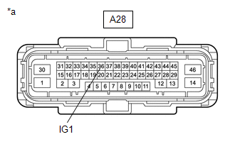 |
|
*a | Front view of wire harness connector
(to Skid Control ECU (Brake Actuator Assembly)) | | |
(c) Measure the voltage according to the value(s) in the table below.
Standard Voltage:
|
Tester Connection | Condition |
Specified Condition |
|
A28-36 (IG1) - Body ground |
Engine switch on (IG) |
11 to 14 V |
| OK |
 | REPLACE SKID CONTROL ECU (BRAKE ACTUATOR ASSEMBLY) |
| NG |
 | REPAIR OR REPLACE HARNESS OR CONNECTOR |
Electric Parking Brake System AUTO Function Circuit
DESCRIPTION
The skid control ECU (brake actuator assembly) receives shift position information from the ECM via CAN communication.
The
electric parking brake system AUTO function (shift-linked function)
automatically releases the parking brake when the following conditions
are met: 1) Engine switch is on (IG), 2) brake pedal is depressed, and
3) shift lever is moved out of P. When the shift lever is moved to P
with these conditions met, the function automatically locks the parking
brake.
The electric parking brake system AUTO
(shift-linked function) automatically engages the parking brake when the
shift lever is moved to P and disengages the parking brake when the
shift lever is moved out of P when the engine switch is on (IG) and the
brake pedal is depressed.
WIRING DIAGRAM
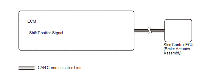
CAUTION / NOTICE / HINT
NOTICE:
- The electric parking brake may still operate up to 20 seconds after the
engine switch is turned off. Before disconnecting connectors or fuses,
turn the engine switch off and wait 20 seconds or more.
- When replacing the skid control ECU (brake actuator assembly), operate
the electric parking brake switch (electric parking brake switch
assembly) as the parking brake indicator light blinks (red) when the
engine switch is first turned on (IG).
PROCEDURE
|
1. | CHECK DTC (SFI SYSTEM) |
(a) Check for DTCs.
Powertrain > Engine > Trouble Codes
|
Result | Proceed to |
|
DTC is not output | A |
|
DTC is output | B |
| A |
 | REPLACE SKID CONTROL ECU (BRAKE ACTUATOR ASSEMBLY) |
| B |
 | GO TO SFI SYSTEM |
Fail-safe Chart
FAIL-SAFE CHART
|
DTC | Trouble Area |
Parking Brake Indicator Light (Red) |
Brake System Warning Light (Yellow) |
Fail-safe Deactivation Condition |
|
C13A5 | Motor current monitor malfunction |
Normal* | Illuminates |
After returning to normal condition, turn engine switch again |
|
C13A6 | Motor open or short circuit malfunction |
Normal* | Illuminates |
After returning to normal condition, turn engine switch again |
|
C13A7 | Actuator assembly malfunction (jamming, spinning, repeated slipping) |
Normal* | Illuminates |
After returning to normal condition, Clear DTCs |
|
C13AA | Electric parking brake high temperature |
Blinks | Does not illuminate |
After 1 minute |
|
C13B0 | ECU malfunction |
Normal (flashes when EEPROM malfunction occurs) |
Illuminates | After returning to normal condition, turn engine switch again |
|
C13B4 | Electric parking brake switch open or short circuit malfunction |
Blinks | Illuminates |
After returning to normal condition, turn engine switch again |
- *: The parking brake indicator light blinks (red) if the electric parking brake switch assembly is pulled or pushed.
Freeze Frame Data
FREEZE FRAME DATA
FREEZE FRAME DATA
HINT:
- When a DTC is stored, the freeze frame data stores the current vehicle (sensor) state as.
- The freeze frame data cannot be cleared or updated until the recorded DTCs are cleared.
Chassis > ABS/VSC/TRAC/EPB |
Tester Display | Measurement Item |
Range | Normal Condition |
Diagnostic Note |
|
Elapsed Time after Freeze Trigger |
Elapsed time after freeze trigger |
Min.: 0 msec, Max.: 510 msec |
- | - |
|
Number of IG ON | Number of times engine switch turned to on (IG) after Freeze Frame Data stored |
0 to 31 | - |
- |
| Buzzer |
Meter buzzer | OFF or ON |
OFF: Buzzer off | No change |
|
Stop Light SW | Stop light switch |
OFF or ON | OFF: Brake pedal released
ON: Brake pedal depressed |
- |
| Parking Brake SW |
Parking brake switch | OFF or ON |
OFF: Parking brake released ON: Parking brake applied |
- |
| Gear Position |
Gear position information |
P/N, R, 1st-8th, Fail or Not R |
Actual gear position |
- |
| Shift Lever Position |
Shift lever position information |
P/N, R, D/M, 1st-6th/B or Fail |
Actual shift lever position |
- |
| Lateral G |
Lateral G | Min.: -25.10 m/s2, Max.: 24.90 m/s2 |
- | During turning: Changes in proportion with lateral acceleration |
|
Forward and Rearward G |
Forward and backward G |
Min.: - 25.10 m/s2, Max.: 24.90 m/s2 |
- | During acceleration/deceleration: Changes in proportion with acceleration |
|
FR Wheel Speed | Front wheel speed sensor RH reading |
Min.: 0 km/h (0 mph), Max.: 326 km/h (202 mph) |
Vehicle stopped: 0 km/h (0 mph) |
When driving at constant speed: No large fluctuations |
|
FL Wheel Speed | Front wheel speed sensor LH reading |
Min.: 0 km/h (0 mph), Max.: 326 km/h (202 mph) |
Vehicle stopped: 0 km/h (0 mph) |
When driving at constant speed: No large fluctuations |
|
RR Wheel Speed | Rear wheel speed sensor RH reading |
Min.: 0 km/h (0 mph), Max.: 326 km/h (202 mph) |
Vehicle stopped: 0 km/h (0 mph) |
When driving at constant speed: No large fluctuations |
|
RL Wheel Speed | Rear wheel speed sensor LH reading |
Min.: 0 km/h (0 mph), Max.: 326 km/h (202 mph) |
Vehicle stopped: 0 km/h (0 mph) |
When driving at constant speed: No large fluctuations |
|
Vehicle Speed | Maximum wheel speed sensor reading |
Min.: 0 km/h (0 mph), Max.: 326 km/h (202 mph) |
Vehicle stopped: 0 km/h (0 mph) |
When driving at constant speed: No large fluctuations |
|
Vehicle Speed Grade | Vehicle speed grade |
Min.: -25.10 m/s2, Max.: 24.90 m/s2 |
Vehicle stopped: 0 m/s2 |
During driving: Changes in proportion with vehicle acceleration/deceleration |
|
Accelerator Opening Angle % |
Percentage of accelerator pedal opening angle |
Min.: 0.0%, Max.: 127.5% |
The accelerator pedal released: 0% |
During accelerator pedal operation: Changes in proportion with the pedal movement |
|
Vehicle Speed (Control Value) |
Vehicle speed (control value) |
Min.: 0.0 km/h (0.0 mph) Max.: 326.4 km/h (202.8 mph) |
- | - |
|
ECU +B1 Voltage | skid control ECU
(brake actuator assembly) +B1 voltage |
0.00 to 20.00 V | 11 to 14 V |
- |
| RH Actuator Motor Input Voltage |
Parking brake motor RH (parking brake actuator assembly RH) input voltage |
0.00 to 20.00 V | - |
- |
| RH Actuator Motor +Terminal Voltage |
Parking brake motor RH (parking brake actuator assembly RH) positive (+) terminal side voltage |
0.00 to 20.00 V | - |
- |
| RH Actuator Motor -Terminal Voltage |
Parking brake motor RH (parking brake actuator assembly RH) negative (-) terminal side voltage |
0.00 to 20.00 V | - |
- |
| LH Actuator Motor Input Voltage |
Parking brake motor LH (parking brake actuator assembly LH) input voltage |
0.00 to 20.00 V | - |
- |
| LH Actuator Motor +Terminal Voltage |
Parking brake motor LH (parking brake actuator assembly LH) positive (+) terminal side voltage |
0.00 to 20.00 V | - |
- |
| LH Actuator Motor -Terminal Voltage |
Parking brake motor LH (parking brake actuator assembly LH) negative (-) terminal side voltage |
0.00 to 20.00 V | - |
- |
| EPB Switch |
Electric parking brake switch (electric parking brake switch assembly) input |
OFF, Lock, Release or Unknown |
OFF: Lock switch and release switch are off Lock: Lock switch on Release: Release switch on |
When
not normal, electric parking brake switch (electric parking brake
switch assembly) release side system may be malfunctioning HINT: EPB stands for electric parking brake. |
|
Auto Mode Request | Auto mode request status |
OFF or ON | - |
- |
| Shift Position |
Position of shift lever |
P, N, R, D or Unknown | P: Shift lever in P
N: Shift lever in N R: Shift lever in R D: Shift lever in D or S |
When not normal, shift position signal system may be malfunctioning |
|
IG Switch | IG power source status |
OFF or ON | OFF: IG power source voltage is not input to skid control ECU (brake actuator assembly)
ON: IG power source voltage is input to skid control ECU (brake actuator assembly) |
- |
| Brake Hold Ready |
Brake hold control permission status |
OFF or ON | - |
- |
| Brake Hold Control Mode |
Brake hold control mode |
OFF, ON, Release or EPB |
OFF: Brake hold control is not operating ON: Brake hold control is operating
Release: Brake hold control is released EPB: Parking brake is locked during brake hold control |
HINT: EPB stands for electric parking brake. |
|
RH Actuator Current Status |
Parking brake actuator assembly RH monitoring current condition |
Valid or Inval | Valid |
- |
| LH Actuator Current Status |
Parking brake actuator assembly LH monitoring current condition |
Valid or Inval | Valid |
- |
| RH Actuator Nut Stroke |
Parking brake actuator assembly RH nut stroke value |
0.000 to 8.160 mm (0 to 0.321 in.) |
- | - |
|
LH Actuator Nut Stroke |
Parking brake actuator assembly LH nut stroke value |
0.000 to 8.160 mm (0 to 0.321 in.) |
- | - |
|
RH Actuator Motor Actual Current |
Parking brake motor RH (parking brake actuator assembly RH) current value |
-5.0362 to 50.5000 A |
- | - |
|
RH Actuator 0 load Current |
Parking brake motor RH (parking brake actuator assembly RH) current calibration value |
-5.0362 to 50.5000 A |
- | - |
|
LH Actuator Motor Actual Current |
Parking brake motor LH (parking brake actuator assembly LH) current value |
-5.0362 to 50.5000 A |
- | - |
|
LH Actuator 0 load Current |
Parking brake motor LH (parking brake actuator assembly LH) current value |
-5.0362 to 50.5000 A |
- | - |
|
Counter of IG ON After EPB Control Cancel |
Number of times the engine switch was turned on (IG) after EPB control was canceled |
0 to 255 Times | - |
- |
| RH Actuator Status |
Parking brake actuator assembly RH condition |
Default,
Lock, Lock Dynamic, Release, Lock Faulty, Unexpected, Lock Standby,
Release Standby, Lock Dynamic Standby, Release Dynamic Standby, Lock
Dynamic Faulty, Lock Standard Control, Lock Dynamic Control, Lock
Control for Prevention Loosen by High Temperature, Lock Control for
Prevention Slipping Down, Re-Lock Control by Switch, Recovery Lock
Control, Lock Control After Dynamic PKB, Release Standard Control,
Release Dynamic Control or Full Release Control |
- | - |
|
LH Actuator Status | Parking brake actuator assembly LH condition |
Default,
Lock, Lock Dynamic, Release, Lock Faulty, Unexpected, Lock Standby,
Release Standby, Lock Dynamic Standby, Release Dynamic Standby, Lock
Dynamic Faulty, Lock Standard Control, Lock Dynamic Control, Lock
Control for Prevention Loosen by High Temperature, Lock Control for
Prevention Slipping Down, Re-Lock Control by Switch, Recovery Lock
Control, Lock Control After Dynamic PKB, Release Standard Control,
Release Dynamic Control or Full Release Control |
- | - |
|
Detailed Freeze DTC | Number of detailed freeze DTCs |
0 to 65535 | - |
- |
| RH Actuator Motor Gradient Current |
Parking brake motor RH (parking brake actuator assembly RH) current gradient |
-5.0362 to 50.5000 A |
- | - |
|
LH Actuator Motor Gradient Current |
Parking brake motor LH (parking brake actuator assembly LH) current gradient |
-5.0362 to 50.5000 A |
- | - |
|
RH Actuator Motor Relay1 |
Parking brake motor relay 1 RH condition |
OFF or ON | - |
- |
| RH Actuator Motor Relay2 |
Parking brake motor relay 2 RH condition |
OFF or ON | - |
- |
| RH Actuator Motor Relay3 |
Parking brake motor relay 3 RH condition |
OFF or ON | - |
- |
| RH Actuator Motor Relay4 |
Parking brake motor relay 4 RH condition |
OFF or ON | - |
- |
| LH Actuator Motor Relay1 |
Parking brake motor relay 1 LH condition |
OFF or ON | - |
- |
| LH Actuator Motor Relay2 |
Parking brake motor relay 2 LH condition |
OFF or ON | - |
- |
| LH Actuator Motor Relay3 |
Parking brake motor relay 3 LH condition |
OFF or ON | - |
- |
| LH Actuator Motor Relay4 |
Parking brake motor relay 4 LH condition |
OFF or ON | - |
- |
| RH Actuator Motor Current High |
Parking brake motor RH (parking brake actuator assembly RH) overcurrent status |
OFF or ON | - |
- |
| RH Actuator Motor Driver Operation Status |
Parking brake motor RH (parking brake actuator assembly RH) driver status |
OK or NG | - |
- |
| LH Actuator Motor Current High |
Parking brake motor LH (parking brake actuator assembly LH) overcurrent status |
OFF or ON | - |
- |
| LH Actuator Motor Driver Operation Status |
Parking brake motor LH (parking brake actuator assembly LH) driver status |
OK or NG | - |
- |
(a)
Using the Techstream, the state of the vehicle (sensors) when the
system is operating or when a DTC was stored can be checked.
How To Proceed With Troubleshooting
CAUTION / NOTICE / HINT
HINT:
*: Use the Techstream.
PROCEDURE
| 1. |
VEHICLE BROUGHT TO WORKSHOP |
|
NEXT |
 | |
| 2. |
CUSTOMER PROBLEM ANALYSIS |
(a) Interview the customer and confirm the problem.
Click here 
|
NEXT |
 | |
| 3. |
INSPECT BATTERY VOLTAGE |
Standard Voltage:
11 to 14 V
- If the voltage is below 11 V, recharge or replace the battery before proceeding to the next step.
|
NEXT |
 | |
| 4. |
CHECK DTC AND FREEZE FRAME DATA* |
(a) Check and record DTCs and freeze frame data.
Chassis > ABS/VSC/TRAC/EPB > Trouble Codes
(b) Clear the DTCs and freeze frame data.
Chassis > ABS/VSC/TRAC/EPB > Clear DTCs
(c) Recheck for DTCs.
(1) Reconfirm the DTCs based on the recorded DTCs and freeze frame data.
Chassis > ABS/VSC/TRAC/EPB > Trouble Codes
(2)
Try to reproduce the problem symptoms based on the recorded DTCs and
freeze frame data, and then check if the DTCs are output again.
| Result |
Proceed to |
| DTCs are not output (Problem symptom occurs.) |
A |
| DTCs are output |
B |
| DTCs are not output (Problem symptom does not occur.) |
C |
HINT:
- Refer to Diagnostic Trouble Code Chart if any DTCs are output.
- When DTCs indicating a CAN communication system malfunction are output,
first troubleshoot and repair the CAN communication system.
| B |
 | GO TO DIAGNOSTIC TROUBLE CODE CHART |
| C |
 | USE SIMULATION METHOD TO CHECK |
|
A |
 | |
| 5. |
PROBLEM SYMPTOMS TABLE |
(a) Proceed to Problem Symptoms Table.
Click here 
| Result |
Proceed to |
| Fault is not listed in Problem Symptoms Table |
A |
| Fault is listed in Problem Symptoms Table |
B |
| B |
 | GO TO STEP 7 |
|
A |
 | |
| 6. |
OVERALL ANALYSIS AND TROUBLESHOOTING* |
(a) Refer to Terminals of ECU.
Click here

(b) Refer to Data List / Active Test.
Click here 
|
NEXT |
 | |
|
NEXT |
 | |
| NEXT |
 | END |
Message Not Displayed on Multi-information Display When AUTO Function Set to ON/OFF
DESCRIPTION
When the AUTO
function is set to ON/OFF, a message is displayed on the
multi-information display in the combination meter assembly.
WIRING DIAGRAM
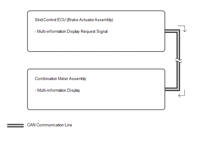
CAUTION / NOTICE / HINT
NOTICE:
- The electric parking brake may still operate up to 20 seconds after the
engine switch is turned off. Before disconnecting connectors or fuses,
turn the engine switch off and wait 20 seconds or more.
- When replacing the skid control ECU (brake actuator assembly), operate
the electric parking brake switch (electric parking brake switch
assembly), as the parking brake indicator light (red) blinks when the
engine switch is first turned on (IG).
PROCEDURE
|
1. | CHECK OPERATION OF AUTO FUNCTION |
(a) Check that the AUTO function operates when the operating conditions are met.
HINT:
Do not use the multi-information display to determine whether the AUTO function is operating or not.
| Result |
Proceed to |
| The AUTO function operates |
A |
| The AUTO function does not operate |
B |
| A |
 | REPLACE COMBINATION METER ASSEMBLY |
| B |
 | GO TO Electric Parking Brake System AUTO Function Circuit |
Parts Location
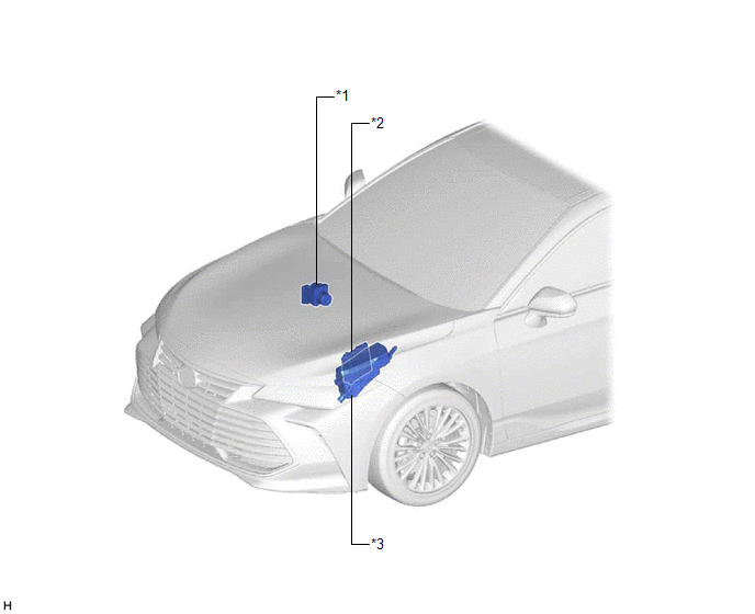
PARTS LOCATION
ILLUSTRATION
|
*1 | SKID CONTROL ECU (BRAKE ACTUATOR ASSEMBLY) |
*2 | ECM |
|
*3 | NO. 1 ENGINE ROOM RELAY BLOCK AND NO. 1 JUNCTION BLOCK ASSEMBLY
- ABS-NO. 1 FUSE - ABS-NO. 2 FUSE |
- | - |
ILLUSTRATION
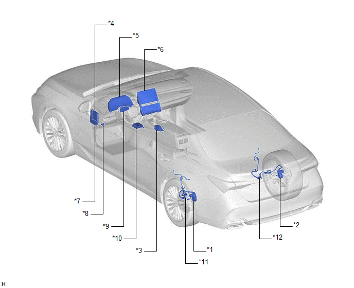
|
*1 | PARKING BRAKE ACTUATOR ASSEMBLY LH |
*2 | PARKING BRAKE ACTUATOR ASSEMBLY RH |
|
*3 | ELECTRIC PARKING BRAKE SWITCH (ELECTRIC PARKING BRAKE SWITCH ASSEMBLY) |
*4 | MAIN BODY ECU (MULTIPLEX NETWORK BODY ECU) |
|
*5 | COMBINATION METER ASSEMBLY |
*6 | RADIO AND DISPLAY RECEIVER ASSEMBLY |
|
*7 | INSTRUMENT PANEL JUNCTION BLOCK ASSEMBLY
- ECU-B NO. 2 FUSE - ECU-IG1 NO. 2 FUSE |
*8 | DLC3 |
|
*9 | AIR CONDITIONING AMPLIFIER ASSEMBLY |
*10 | DECELERATION SENSOR (AIRBAG ECU ASSEMBLY) |
|
*11 | NO. 2 PARKING BRAKE WIRE ASSEMBLY |
*12 | NO. 1 PARKING BRAKE WIRE ASSEMBLY |
Precaution
PRECAUTION
PRECAUTION FOR DISCONNECTING CABLE FROM NEGATIVE BATTERY TERMINAL
NOTICE:
When
disconnecting the cable from the negative (-) battery terminal,
initialize the following system(s) after the cable is reconnected.
|
System | See Procedure |
|
Lane Departure Alert System (w/ Steering Control) |
 |
|
Intelligent Clearance Sonar System |
|
Parking Assist Monitor System |
|
Panoramic View Monitor System |
|
Pre-collision System |
|
Lighting System (for Gasoline Model with Cornering Light) |
TROUBLESHOOTING PRECAUTIONS
(a)
When inspecting the rear brakes, disconnect the connector of the
parking brake actuator assembly or disconnect the cable from the
negative (-) battery terminal.
CAUTION:
- Do not perform the rear brake inspection while either the skid control
ECU (brake actuator assembly) connector or the negative (-) battery
terminal are connected.
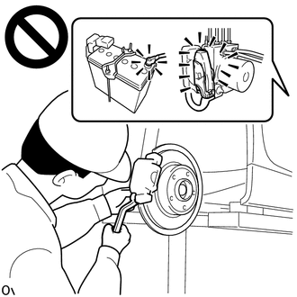
- The rear disc brake piston could operate, resulting in an accident such as hands being caught.
(b) The electric parking brake may
still operate up to 20 seconds after the engine switch is turned off.
Before disconnecting connectors or fuses, turn the engine switch off and
wait 20 seconds or more.
(c) If a component has
been removed and installed, confirm that the system operates normally by
checking for DTCs after installation has been completed.
HANDLING PRECAUTIONS
(a)
When tilting the vehicle to perform work after parking the vehicle on a
level surface, the braking force may not be sufficient. Make sure to
pull the electric parking brake switch (electric parking brake switch
assembly) to the lock side 2 times (2 lock operations).
HINT:
- The electric parking brake system determines the amount of force used to
operate the parking brake according to the tilt angle detected by the
deceleration sensor (airbag ECU assembly).
- When the parking brake indicator (red) is illuminated after the electric
parking brake switch (electric parking brake switch assembly) has been
pulled to the lock side, the maximum amount of braking force is applied
if the electric parking brake switch (electric parking brake switch
assembly) is pulled to the lock side one more time.
(b) The parking brake indicator
light blinks (red) when the engine switch is turned on (IG) after
replacing the skid control ECU (brake actuator assembly). Operate the
electric parking brake switch (electric parking brake switch assembly)
to turn off the parking brake indicator light.
PRECAUTIONS FOR TOWING VEHICLES
(a) For towing precautions: Click here 
PARKING BRAKE FORCED RELEASE METHOD
(a) For the parking brake forced release method: Click here

Problem Symptoms Table
PROBLEM SYMPTOMS TABLE
HINT:
- Use the table below to help determine the cause of problem symptoms. If
multiple suspected areas are listed, the potential causes of the
symptoms are listed in order of probability in the "Suspected Area"
column of the table. Check each symptom by checking the suspected areas
in the order they are listed. Replace parts as necessary.
- Inspect the fuses and relays related to this system before inspecting the suspected areas below.
|
Symptom | Suspected Area |
Link |
| Electric parking brake does not operate |
Proceed to "Electric Parking Brake does not Operate" |
 |
|
Parking brake indicator light does not illuminate (red) or turn off when parking brake is manually engaged and disengaged |
Proceed to "Electric Parking Brake does not Operate" |
 |
|
Electric
parking brake AUTO function (shift-linked function) does not operate
(shift-linked parking brake does not lock or release) |
Proceed to "Electric Parking Brake AUTO Function Circuit" |
 |
|
Message not displayed on multi-information display when AUTO function set to ON/OFF |
Proceed to "Message Not Displayed on Multi-information Display When AUTO Function Set to ON/OFF" |
 |
|
Electric
parking brake switch indicator light on electric parking brake switch
(electric parking brake switch assembly) does not illuminate or turn off
when lock and release operations are performed |
Electric parking brake switch indicator light drive circuit |
 |
|
Wire
harness or connector (electric parking brake switch (electric parking
brake switch assembly) - skid control ECU (brake actuator assembly)) |
- |
| Electric parking brake switch (electric parking brake switch assembly) |
 |
|
Skid control ECU (brake actuator assembly) |
 |
System Diagram
SYSTEM DIAGRAM
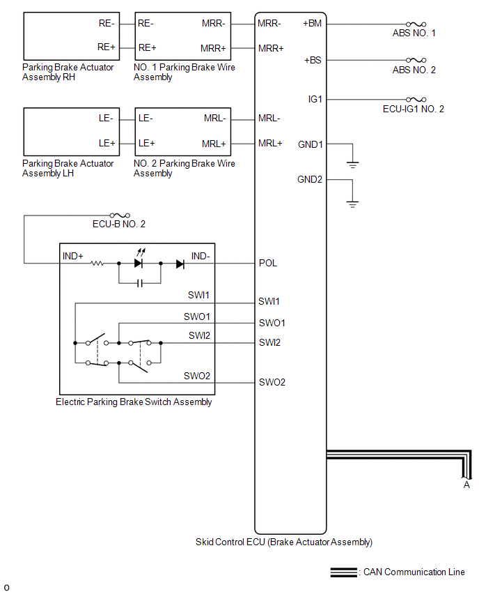
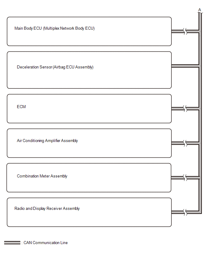
Terminals Of Ecu
TERMINALS OF ECU
CHECK SKID CONTROL ECU (BRAKE ACTUATOR ASSEMBLY)

|
*a | Front view of wire harness connector (to Skid Control ECU (Brake Actuator Assembly)) |
- | - |
(a) Disconnect the A28 skid control ECU (brake actuator assembly) connector.
(b) Measure the voltage and resistance according to the value (s) in the table below.
|
Terminal No. (Symbol) | Wiring Color |
Terminal Description | Condition |
Specified Condition |
|
A28-1 (+BM) - Body ground |
B - Body ground | Parking brake power supply |
Always | 11 to 14 V |
|
A28-30 (+BS) - Body ground |
G - Body ground | Parking brake motor power supply |
Always | 11 to 14 V |
|
A28-36 (IG1) - Body ground |
B - Body ground | IG power supply |
Engine switch on (IG) |
11 to 14 V |
|
A28-46 (GND1) - Body ground |
W-B - Body ground | Ground |
Always | Below 1 Ω |
|
A28-14 (GND2) - Body ground |
W-B - Body ground | Ground |
Always | Below 1 Ω |
|
A28-2 (MRR+) - Body ground |
Y - Body ground | Parking brake motor RH (parking brake actuator assembly RH) (+) |
- | - |
|
A28-3 (MRR-) - Body ground |
L - Body ground | Parking brake motor RH (parking brake actuator assembly RH) (-) |
- | - |
|
A28-13 (MRL+) - Body ground |
G - Body ground | Parking brake motor LH (parking brake actuator assembly LH) (+) |
- | - |
|
A28-12 (MRL-) - Body ground |
W - Body ground | Parking brake motor LH (parking brake actuator assembly LH) (-) |
- | - |
|
A28-35 (POL) - Body ground |
L - Body ground | Electric parking brake switch indicator light |
- | - |
|
A28-31 (SWI1) - Body ground |
P - Body ground | Electric parking brake switch (electric parking brake switch assembly) |
- | - |
|
A28-15 (SWI2) - Body ground |
W - Body ground | Electric parking brake switch (electric parking brake switch assembly) |
- | - |
|
A28-32 (SWO1) - Body ground |
SB - Body ground | Electric parking brake switch (electric parking brake switch assembly) |
- | - |
|
A28-16 (SWO2) - Body ground |
V - Body ground | Electric parking brake switch (electric parking brake switch assembly) |
- | - |
|
A28-5 (CANH) - Body ground |
Y - Body ground | CAN communication line H |
- | - |
|
A28-19 (CANL) - Body ground |
W - Body ground | CAN communication line L |
- | - |
Test Mode Procedure
TEST MODE PROCEDURE
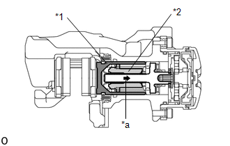
REAR BRAKE PAD REPLACEMENT MODE
|
*1 | Rear Disc Brake Piston |
|
*2 | Nut |
|
*a | The nut moves inward in pad replacement mode |
HINT:
When
replacing the rear disc brake pad and rear disc, since the nut inside
the rear disc brake cylinder assembly is in an advanced position, it is
necessary to move the nut back inside the cylinder. The nut can be moved
back using pad replacement mode.
(a) Pad replacement mode
When Using the Techstream:
- Turn the engine switch off.
- Connect the Techstream to the DLC3.
- Turn the engine switch on (IG).
- Turn the Techstream on.
- Enter the following menus: Chassis / ABS/VSC/TRAC/EPB / Utility / Check Mode
- Follow the Techstream display and select "Next".
- Push and hold the electric parking brake switch (electric parking brake
switch assembly) to the release side for 5 seconds or more.
NOTICE:
- Make sure to perform this procedure with the engine switch on (IG).
- Make sure that the brake pedal is not depressed when performing this procedure.
- When the system changes to pad replacement mode, DTC C13A7 may be
stored. If the DTC is stored, clear the DTCs after the procedure (rear
brake pad replacement, etc.) is complete.
HINT:
The
parking brake indicator light flashes (red) (0.25 seconds intervals).
After a short time, the parking brake actuator assembly operates (if the
parking brake is engaged, the motor will operate to disengage the
parking brake, and then will operate again). Once the parking brake
actuator assembly is in the pad replacement position, the parking brake
indicator light flashes (red) (1 second intervals).
Chassis > ABS/VSC/TRAC/EPB > Utility |
Tester Display |
| Check Mode |
When not Using the Techstream:
- Turn the engine switch off.
- Turn the engine switch on (IG).
- Within 8 seconds, operate the electric parking brake switch (electric
parking brake switch assembly) to perform 3 lock side ON operations
(from off (release) to on (pull)) and then 3 release side ON operations
(from off (release) to on (push)).
NOTICE:
- If the operation is performed too quickly, the system may not respond.
If the system does not respond, perform the operation again at a slower
speed.
- The parking brake must be released.
HINT:
The parking brake indicator light (red) flashes (0.25 seconds intervals).
- Push and hold the electric parking brake switch (electric parking brake
switch assembly) to the release side for 5 seconds or more.
NOTICE:
- Make sure to perform this procedure with the engine switch on (IG).
- Make sure that the brake pedal is not depressed when performing this procedure.
- When the system changes to pad replacement mode, DTC C13A7 may be
stored. If the DTC is stored, clear the DTCs after the procedure (rear
brake pad replacement, etc.) is complete.
HINT:
After a
short time passes, the parking brake actuator assembly operates (if
operated from the parking brake locked condition, the motor of the
parking brake actuator assembly is temporarily stopped after being
operated, and then operation starts again), and once the assembly
finishes operating, the parking brake indicator light (red) flashes
slowly (1 second intervals). (Nut moves back inside the cylinder and
system enters pad replacement mode).
(b) Turn the engine switch off.
NOTICE:
Do
not operate the electric parking brake switch (electric parking brake
switch assembly) until the procedure is complete. If operated, the
system will return to its normal condition.
When Using the Techstream:
- Disconnect the Techstream from the DLC3.
(c) Normal condition recovery
(1)
After the procedure (rear brake pad replacement, etc.) is complete,
turn the engine switch on (IG) and pull the electric parking brake
switch (integration control and panel assembly) to the lock side for 5
seconds or more.
NOTICE:
- When performing work (replacing the rear brake pad, etc.), do not
operate the electric parking brake switch (electric parking brake switch
assembly) or turn the engine switch on (IG) and operate the shift
lever. If the electric parking brake switch (electric parking brake
switch assembly) or shift lever is operated, the parking brake may
operate and the rear disc brake piston may fall off. Also, make sure to
disconnect the connector of the parking brake actuator assembly or
disconnect the cable from the negative (-) battery terminal.
- When DTC C13A7 is stored, clear the DTCs.


