Components
COMPONENTS
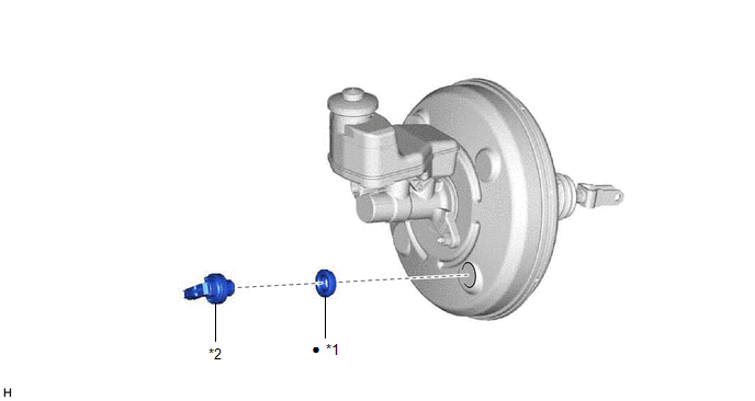
ILLUSTRATION
|
*1 | CHECK VALVE GROMMET |
*2 | VACUUM WARNING SWITCH ASSEMBLY |
|
â—Ź | Non-reusable part |
- | - |
Installation
INSTALLATION
PROCEDURE
1. INSTALL CHECK VALVE GROMMET
(a) Install a new check valve grommet to the brake booster assembly.
2. INSTALL VACUUM WARNING SWITCH ASSEMBLY
(a) Install the vacuum warning switch assembly to the brake booster assembly as shown in the illustration.
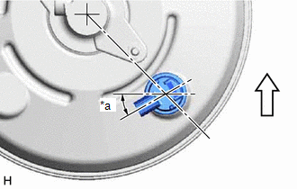
|
*a | 30° +/- 20° |
 | Up |
(b) Connect the connector to the vacuum warning switch assembly.
3. INSTALL BATTERY
Click here 
On-vehicle Inspection
ON-VEHICLE INSPECTION
PROCEDURE
1. INSPECT BRAKE FLUID LEVEL IN RESERVOIR
Click here

2. INSPECT BRAKE BOOSTER ASSEMBLY
Click here
3. INSPECT VACUUM WARNING SWITCH ASSEMBLY
(a) Start the engine and stop it after 1 or 2 minutes.
(b) Remove the battery.
Click here
(c) Disconnect the connector from the vacuum warning switch assembly.
(d) Measure the resistance of the vacuum warning switch assembly.
Standard Resistance:
10 kΩ or higher
(e)
With the engine stopped, depress the brake pedal several times to
release vacuum from the brake booster assembly, and measure the
resistance of the vacuum warning switch assembly.
Standard Resistance:
Below 1 Ω
(f) Connect the connector to the vacuum warning switch assembly.
(g) Install the battery.
Click here
Removal
REMOVAL
CAUTION / NOTICE / HINT
The
necessary procedures (adjustment, calibration, initialization or
registration) that must be performed after parts are removed and
installed, or replaced during vacuum warning switch assembly
removal/installation are shown below.+
Necessary Procedures After Parts Removed/Installed/Replaced |
Replaced Part or Performed Procedure |
Necessary Procedure | Effect/Inoperative Function when Necessary Procedure not Performed |
Link |
|
*: When performing learning using the Techstream.
Click here  |
|
Battery terminal is disconnected/reconnected |
Perform steering sensor zero point calibration |
Lane departure alert system (w/ Steering Control) |
|
|
Pre-collision system |
|
Intelligent Clearance Sonar System* |
|
Lighting System (for Gasoline Model with Cornering Light) |
|
Memorize steering angle neutral point |
Parking assist monitor system |
|
|
Panoramic View Monitor System |
|
PROCEDURE
1. PRECAUTION
NOTICE:
After
turning the engine switch off, waiting time may be required before
disconnecting the cable from the negative (-) battery terminal.
Therefore, make sure to read the disconnecting the cable from the
negative (-) battery terminal notices before proceeding with work.
Click here
2. REMOVE BATTERY
Click here
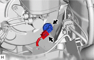
3. REMOVE VACUUM WARNING SWITCH ASSEMBLY
| (a) Disconnect the connector from the vacuum warning switch assembly. |
|
(b) Remove the vacuum warning switch assembly from the brake booster assembly.
4. REMOVE CHECK VALVE GROMMET
(a) Remove the check valve grommet from the brake booster assembly.