Components
COMPONENTS
ILLUSTRATION
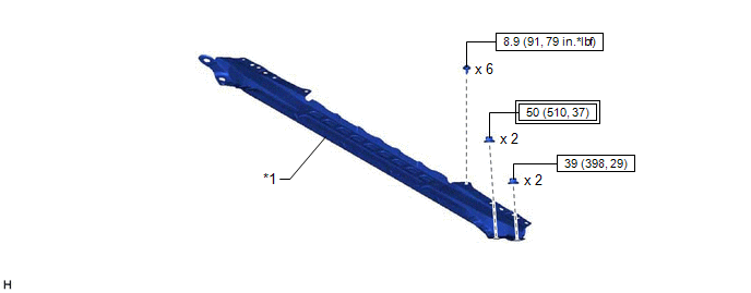
|
*1 | FRONT CENTER UPPER SUSPENSION BRACE SUB-ASSEMBLY |
- | - |
 |
Tightening torque for "Major areas involving basic vehicle performance such as moving/turning/stopping": N*m (kgf*cm, ft.*lbf) |
 |
N*m (kgf*cm, ft.*lbf): Specified torque |
ILLUSTRATION
|
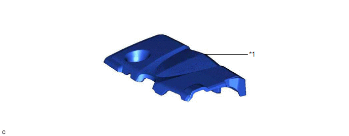
*1 | NO. 1 ENGINE COVER SUB-ASSEMBLY |
- | - |
ILLUSTRATION
|
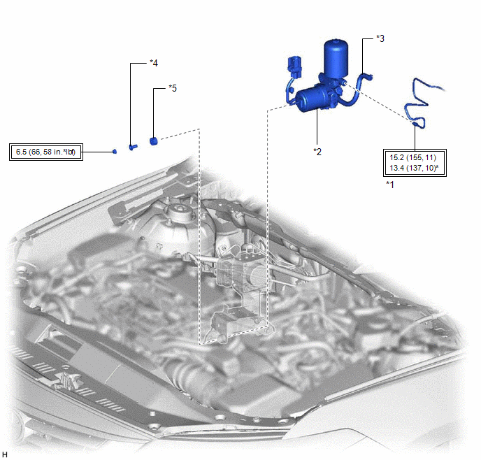
*1 | ACCUMULATOR TO BRAKE MASTER CYLINDER TUBE |
*2 | BRAKE BOOSTER PUMP ASSEMBLY |
|
*3 | NO. 2 BRAKE ACTUATOR HOSE |
*4 | BRAKE ACTUATOR CASE COLLAR |
|
*5 | BRAKE BOOSTER PUMP BUSHING |
- | - |
 |
Tightening torque for "Major areas involving basic vehicle performance such as moving/turning/stopping": N*m (kgf*cm, ft.*lbf) |
* | For use with a union nut wrench |
ILLUSTRATION
|
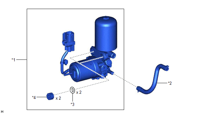
*1 | BRAKE BOOSTER PUMP ASSEMBLY |
*2 | NO. 2 BRAKE ACTUATOR HOSE |
|
*3 | BRAKE BOOSTER PUMP COLLAR |
*4 | BRAKE BOOSTER PUMP BUSHING |
Disposal
DISPOSAL
PROCEDURE
1. DISPOSE OF BRAKE BOOSTER PUMP ASSEMBLY
(a) Remove the accumulator from the brake booster pump assembly.
(b) Secure the accumulator in a vise.
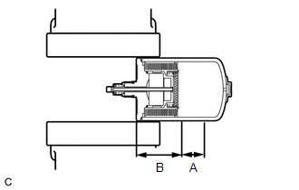
(c) Using a hacksaw, make a cut in the side of the accumulator within location (A) to release the high-pressure gas.
|
Location | Length |
|
A | 25 mm (0.984 in.) |
|
B | 60 mm (2.36 in.) |
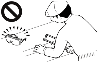
- Wear protective glasses.
- Small pieces of metal may fly out when cutting into the accumulator. Put
a cloth over the hacksaw when cutting the accumulator. Cut the
accumulator slowly so that the gas will be released gradually.
HINT:
Nitrogen gas, which is colorless, odorless and harmless, will be discharged.
Inspection
INSPECTION
PROCEDURE
1. INSPECT BRAKE BOOSTER PUMP ASSEMBLY
| (a) Measure the resistance according to the value(s) in the table below.
Standard Resistance: |
Tester Connection | Condition |
Specified Condition | |
2 (BM1) - 4 (GND1) |
Always | 10 Ω or less | |
1 (BM2) - 3 (GND2) |
Always | 10 Ω or less | |
2 (BM1) - 1 (BM2) |
Always | Below 1 Ω | |
4 (GND1) - 3 (GND2) |
Always | Below 1 Ω | |
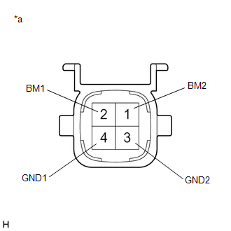 |
|
*a | Component without harness connected
(Brake Booster Pump Assembly) | | |
Installation
INSTALLATION
PROCEDURE
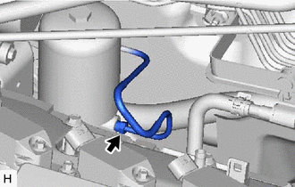
1. INSTALL NO. 2 BRAKE ACTUATOR HOSE
(a) Install the No. 2 brake actuator hose to the brake booster pump assembly and slide the clip to secure it.
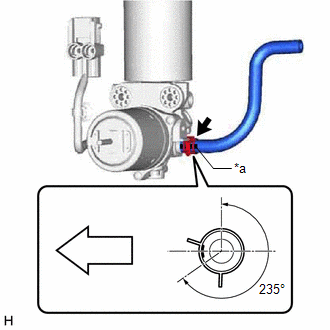
|
*a | Identification Mark |
 |
Front of the vehicle |
NOTICE:
- Make sure to connect the No. 2 brake actuator hose with its identification mark facing the front of the vehicle.
- Install the clip within the range shown in the illustration.
2. INSTALL BRAKE BOOSTER PUMP ASSEMBLY
| (a)
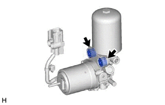
Install the 2 brake booster pump collars and 2 brake booster pump
bushings to the brake booster pump assembly as shown in the
illustration. HINT: Perform this procedure only when replacement of the brake booster pump collars or brake booster pump bushings is necessary. |
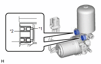 |
|
*1 | Brake Booster Pump Collar | |
*2 | Brake Booster Pump Bushing | | |
(b)
Install the brake booster pump assembly, brake booster pump bushing and
brake actuator case collar to the brake actuator bracket assembly as
shown in the illustration.
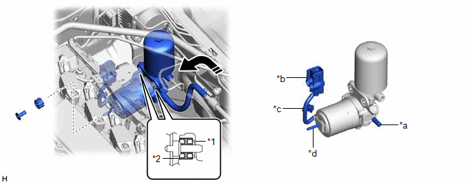
|
*1 | Brake Booster Pump Collar |
*2 | Brake Booster Pump Bushing |
|
*a | Union |
*b | Connector |
|
*c | Wire Harness |
*d | Stud |
 |
Install in this Direction |
- | - |
NOTICE:
- Be careful not to allow brake fluid to enter the connector.
- Do not apply excessive force to the brake lines.
- When installing the brake booster pump assembly to the brake actuator
bracket assembly, confirm that the 2 brake booster pump bushings and 2
brake booster pump collars are installed to the brake booster pump
assembly.
- Do not drop the brake booster pump assembly when carrying it.
- If installing a new brake booster pump assembly, do not remove the hole
plugs before connecting the brake lines because the brake booster pump
assembly is filled with brake fluid.
- Do not carry the brake booster pump assembly by the parts shown in the illustration.
(c) Install the nut.
Torque:
6.5 N·m {66 kgf·cm, 58 in·lbf}
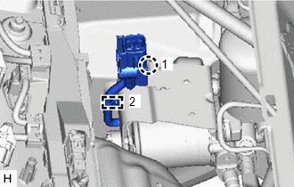
| (d) Engage the claw and clamp to install the brake booster pump assembly wire harness to the brake actuator bracket assembly.
NOTICE: Engage the claw and clamp in the order shown in the illustration. |
|
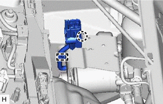
(e) Connect the connector to the brake booster pump assembly and lock the lock lever as shown in the illustration.
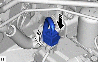
 | Connect the connector |
 |
Lock the lock lever |
NOTICE:
- Make sure that the connector is locked securely.
- Make sure that the connector can be connected smoothly.
- Do not allow water, oil or dirt to enter the connector.
3. CONNECT ACCUMULATOR TO BRAKE MASTER CYLINDER TUBE
| (a) Using a union nut wrench, connect the accumulator to brake master cylinder tube to the brake booster pump assembly.
Torque: Specified tightening torque : 15.2 N·m {155 kgf·cm, 11 ft·lbf}
NOTICE:
- Do not kink or damage the accumulator to brake master cylinder tube.
- Do not allow the accumulator to brake master cylinder tube to twist or
interfere with other parts or the vehicle body during tightening.
- Do not allow any foreign matter such as dirt or dust to enter the
accumulator to brake master cylinder tube from the connecting parts.
HINT:
|
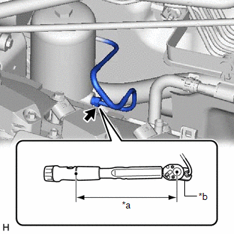 |
|
*a | Torque Wrench Fulcrum Length | |
*b | Union Nut Wrench | | |
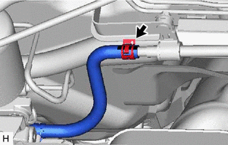
4. CONNECT NO. 2 BRAKE ACTUATOR HOSE
(a) Connect the No. 2 brake actuator hose to the No. 1 brake actuator tube and slide the clip to secure it.
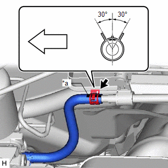
|
*a | Identification Mark |
 |
Front of the vehicle |
NOTICE:
- When connecting the No. 2 brake actuator hose, face the identification mark up.
- Install the clip within the range shown in the illustration.
5. BLEED NO. 1 BRAKE ACTUATOR TUBE
Click here

6. FILL RESERVOIR WITH BRAKE FLUID
7. CONNECT CABLE TO NEGATIVE AUXILIARY BATTERY TERMINAL
Click here

8. BLEED BRAKE SYSTEM
Click here

9. INSTALL NO. 1 ENGINE COVER SUB-ASSEMBLY
Click here 
10. INSTALL FRONT CENTER UPPER SUSPENSION BRACE SUB-ASSEMBLY
Click here 
11. INSTALL COWL TOP VENTILATOR LOUVER SUB-ASSEMBLY
Click here 
Removal
REMOVAL
CAUTION / NOTICE / HINT
The
necessary procedures (adjustment, calibration, initialization, or
registration) that must be performed after parts are removed, installed,
or replaced during brake booster pump assembly removal/installation are
shown below.
Necessary Procedures After Parts Removed/Installed/Replaced |
Replaced Part or Performed Procedure |
Necessary Procedure | Effect/Inoperative Function when Necessary Procedure not Performed |
Link |
|
*: When performing learning using the Techstream.
Click here  |
|
Auxiliary battery terminal is disconnected/reconnected |
Perform steering sensor zero point calibration |
Lane Departure Alert System (w/ Steering Control) |
 |
|
Pre-collision System |
|
Intelligent Clearance Sonar System* |
|
Lighting System (for HV Model with Cornering Light) |
|
Memorize steering angle neutral point |
Parking Assist Monitor System |
 |
|
Panoramic View Monitor System |
 |
NOTICE:
While
the auxiliary battery is connected, even if the power switch is off,
the brake control system activates when the brake pedal is depressed or
any door courtesy switch turns on. Therefore, when servicing the brake
system components, do not operate the brake pedal or open/close the
doors while the auxiliary battery is connected.
PROCEDURE
1. PRECAUTION
NOTICE:
After
turning the power switch off, waiting time may be required before
disconnecting the cable from the negative (-) auxiliary battery
terminal. Therefore, make sure to read the disconnecting the cable from
the negative (-) auxiliary battery terminal notices before proceeding
with work.
Click here 
2. PERFORM ACCUMULATOR PRESSURE ZERO DOWN
Click here 
3. REMOVE COWL TOP VENTILATOR LOUVER SUB-ASSEMBLY
Click here 
4. REMOVE FRONT CENTER UPPER SUSPENSION BRACE SUB-ASSEMBLY
Click here 
5. REMOVE NO. 1 ENGINE COVER SUB-ASSEMBLY
Click here 
6. DRAIN BRAKE FLUID
NOTICE:
If brake fluid leaks onto any painted surface, immediately wash it off.
7. DISCONNECT NO. 2 BRAKE ACTUATOR HOSE
| (a) Slide the clip and disconnect the No. 2 brake actuator hose from the No. 1 brake actuator tube. |
|
8. DISCONNECT ACCUMULATOR TO BRAKE MASTER CYLINDER TUBE
| (a) Using a union nut wrench, disconnect the accumulator to brake master cylinder tube from the brake booster pump assembly.
NOTICE:
- Do not kink or damage the accumulator to brake master cylinder tube.
- Do not allow any foreign matter such as dirt or dust to enter the
accumulator to brake master cylinder tube from the connecting parts.
| |
9. REMOVE BRAKE BOOSTER PUMP ASSEMBLY
(a) Release the lock lever and disconnect the connector from the brake booster pump assembly as shown in the illustration.
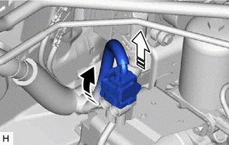
 | Release the lock lever |
 |
Disconnect the connector |
NOTICE:
Be careful not to allow any brake fluid to enter the connector.
| (b)
Disengage the claw and clamp to separate the brake booster pump
assembly wire harness from the brake actuator bracket assembly. | |
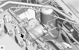
| (c) Remove the nut from the brake booster pump assembly. |
|
(d)
Remove the brake booster pump assembly, brake booster pump bushing and
brake actuator case collar from the brake actuator bracket assembly as
shown in the illustration.
NOTICE:
- Do not apply excessive force to the brake lines.
- Do not carry the brake booster pump assembly by the parts shown in the illustration.
- Do not drop the brake booster pump assembly when carrying it.
- Be careful not to allow brake fluid to enter the connector.
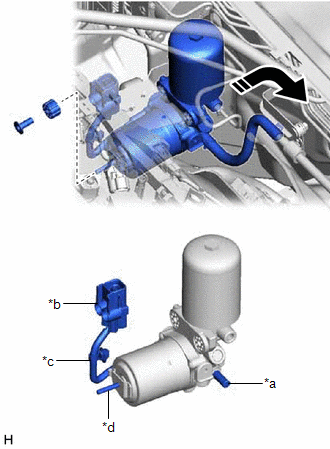
|
*a | Union |
|
*b | Connector |
|
*c | Wire Harness |
|
*d | Stud |
 |
Remove in this Direction |
| (e) Remove the 2 brake booster pump collars and 2 brake booster pump bushings from the brake booster pump assembly.
HINT: Perform this procedure only when replacement of the brake booster pump collars or brake booster pump bushings is necessary. |
|
10. REMOVE NO. 2 BRAKE ACTUATOR HOSE
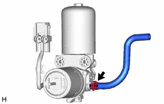
| (a) Slide the clip and remove the No. 2 brake actuator hose from the brake booster pump assembly. |
|


