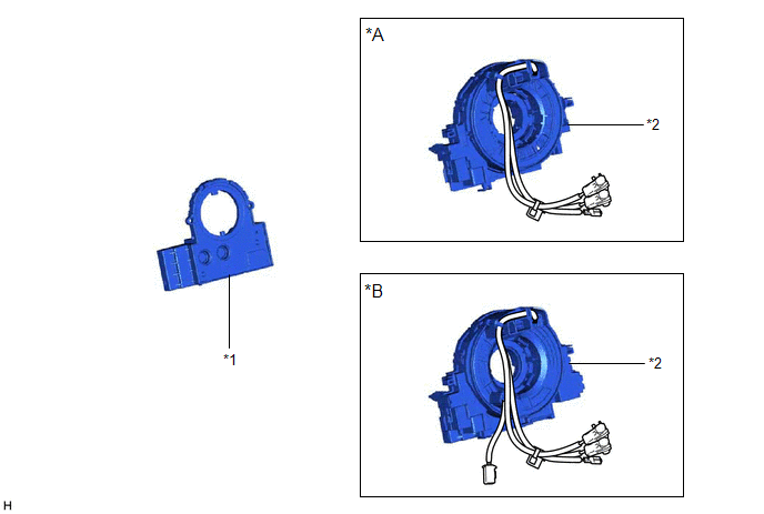
COMPONENTS ILLUSTRATION *A w/o Heated Steering Wheel System *B w/ Heated Steering Wheel System *1 STEERING SENSOR *2 SPIRAL CABLE SUB-ASSEMBLY INSTALLATION CAUTION / NOTICE / HINT NOTICE: A
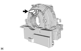
lock pin is installed to a new steering sensor. Do not remove the lock
pin before the steering sensor is installed to the spiral cable
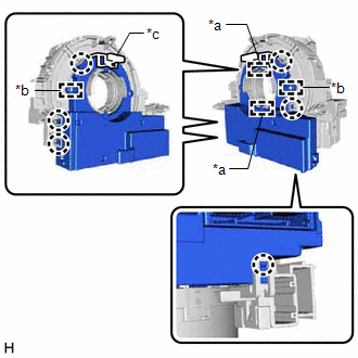
sub-assembly. PROCEDURE 1. INSPECT SPIRAL CABLE SUB-ASSEMBLY Click here 2. INSTALL STEERING SENSOR (a) Align the 2 pins and 2 guides, and engage the 6 claws to install the steering sensor to the spiral cable sub-assembly. NOTICE: *a Guide *b Pin *c Lock Pin (b) Remove the lock pin from the steering sensor. 3. INSTALL SPIRAL CABLE WITH SENSOR SUB-ASSEMBLY Click here
REMOVAL CAUTION / NOTICE / HINT The
necessary procedures (adjustment, calibration, initialization or
registration) that must be performed after parts are removed and
installed, or replaced during steering sensor removal/installation are
shown below. Replaced Part or Performed Procedure Necessary Procedure Effect/Inoperative Function when Necessary Procedure not Performed Link Click here Auxiliary battery terminal is disconnected/reconnected Perform steering sensor zero point calibration Lane departure alert system (w/ Steering Control) Pre-collision system Intelligent Clearance Sonar System* Lighting System (for HV Model with Cornering Light) Memorize steering angle neutral point Parking assist monitor system Panoramic View Monitor System Replacement of steering sensor Steering angle zero point learning (Initialize intelligent clearance sonar system)
Parking Assist Monitor System for Initialization: for Calibration:
Steering angle zero point learning (Initialize panoramic view monitor system) Panoramic View Monitor System for Initialization: for Calibration:
Replaced Part or Performed Procedure Necessary Procedure Effect/Inoperative Function when Necessary Procedure not Performed Link Click here Battery terminal is disconnected/reconnected Perform steering sensor zero point calibration Lane departure alert system (w/ Steering Control) Pre-collision system Intelligent Clearance Sonar System* Lighting System (for Gasoline Model with Cornering Light) Memorize steering angle neutral point Parking assist monitor system Panoramic View Monitor System Replacement of steering sensor Steering angle zero point learning (Initialize intelligent clearance sonar system)
Parking Assist Monitor System for Initialization: for Calibration:
Steering angle zero point learning (Initialize panoramic view monitor system) Panoramic View Monitor System for Initialization: for Calibration:
PROCEDURE 1. REMOVE SPIRAL CABLE WITH SENSOR SUB-ASSEMBLY Click here
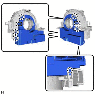
2. REMOVE STEERING SENSOR (a) Disengage the 6 claws and 2 pins, and remove the steering sensor from the spiral cable sub-assembly. NOTICE: Do not damage the claws and pins of the spiral cable sub-assembly.Components

Installation


Removal
Necessary Procedures After Parts Removed/Installed/Replaced (for Gasoline Model:)
*: When performing learning using the Techstream.


*: When performing learning using the Techstream.


Toyota Avalon (XX50) 2019-2022 Service & Repair Manual > Sfi System: Evaporative Emission System Leak Detected (Large Leak) (P045500,P045600). Fuel Level Sensor "A" Circuit Short to Battery (P046012,P046014). Vehicle Speed Sensor "A" No Signal (P050031)
Evaporative Emission System Leak Detected (Large Leak) (P045500,P045600) DTC SUMMARY DTC No. Detection Item DTC Detection Condition Trouble Area MIL Memory Note P045500 Evaporative Emission System Leak Detected (Large Leak) Leak detection pump creates negative pressure (vacuum) in EVAP system and EV ...