DESCRIPTION The skid
control ECU (brake booster with master cylinder assembly) is connected
to the combination meter assembly via CAN communication. If
the skid control ECU (brake booster with master cylinder assembly)
stores a DTC, the slip indicator light comes on in the combination meter
assembly. The slip indicator light blinks during ABS, VSC and/or TRAC operation. When the system is malfunctioning, the slip indicator light comes on to warn the driver. Click here WIRING DIAGRAM Refer to Brake Control Warning Light Remains ON. Click here
CAUTION / NOTICE / HINT NOTICE: After
replacing the skid control ECU (brake booster with master cylinder
assembly), perform linear solenoid valve offset learning, ABS holding
solenoid valve learning, yaw rate and acceleration sensor zero point
calibration and system information memorization after performing "Reset
Memory". Click here PROCEDURE 1. CHECK CAN COMMUNICATION SYSTEM (a) Check if CAN communication system DTCs are output. Click here Result Proceed to DTCs are not output. A DTCs are output. B INSPECT CAN COMMUNICATION SYSTEM 2. CHECK IF BRAKE BOOSTER WITH MASTER CYLINDER ASSEMBLY CONNECTOR IS SECURELY CONNECTED (a) Check if the skid control ECU (brake booster with master cylinder assembly) connector is securely connected. OK: The connector is securely connected. CONNECT CONNECTOR TO BRAKE BOOSTER WITH MASTER CYLINDER ASSEMBLY CORRECTLY 3. CHECK AUXILIARY BATTERY (a) Check the auxiliary battery voltage. Standard Voltage: Tester Connection Condition Specified Condition Auxiliary battery Power switch on (IG) 11 to 14 V Auxiliary battery Power switch on (READY) 11 to 15.5 V CHARGE OR REPLACE AUXILIARY BATTERY 4. READ VALUE USING TECHSTREAM (SLIP INDICATOR LIGHT) (a) Select the Data List on the Techstream. Click here
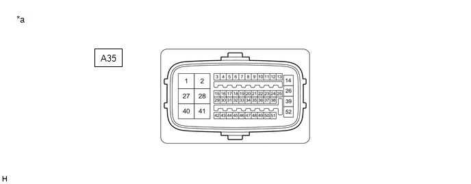
Tester Display Measurement Item Range Normal Condition Diagnostic Note Slip Indicator Light Slip indicator light ON or OFF ON: Indicator light on OFF: Indicator light off - Tester Display Slip Indicator Light (b) Check the Techstream display condition of the slip indicator light. Result Proceed to ON is displayed. A OFF is displayed. B REPLACE BRAKE BOOSTER WITH MASTER CYLINDER ASSEMBLY INSPECT METER / GAUGE SYSTEM SYSTEM DIAGRAM Transmitting ECU (Transmitter) Receiving ECU Signal Communication Method Skid control ECU (Brake booster with master cylinder assembly) Power steering ECU (Rack and pinion power steering gear assembly) CAN communication line Main body ECU (Multiplex network body ECU) Skid control ECU (Brake booster with master cylinder assembly) Driver side seat belt buckle switch signal CAN communication line Skid control ECU (Brake booster with master cylinder assembly) Hybrid vehicle control ECU CAN communication line Hybrid vehicle control ECU Skid control ECU (Brake booster with master cylinder assembly) CAN communication line Skid control ECU (Brake booster with master cylinder assembly) Steering angle sensor Steering angle sensor request signal CAN communication line Steering angle sensor Skid control ECU (Brake booster with master cylinder assembly) Steering angle sensor signal CAN communication line Skid control ECU (Brake booster with master cylinder assembly) Yaw rate and acceleration sensor (Airbag ECU assembly) Yaw rate and acceleration request signal CAN communication line Yaw rate and acceleration sensor (Airbag ECU assembly) Skid control ECU (Brake booster with master cylinder assembly) Yaw rate and acceleration signal CAN communication line Skid control ECU (Brake booster with master cylinder assembly) Parking brake ECU (Brake actuator assembly) CAN communication line Parking brake ECU (Brake actuator assembly) Skid control ECU (Brake booster with master cylinder assembly) CAN communication line Skid control ECU (Brake booster with master cylinder assembly) Combination meter assembly CAN communication line Skid control ECU (Brake booster with master cylinder assembly) Certification ECU (Smart key ECU assembly) CAN communication line Certification ECU (Smart key ECU assembly) Skid control ECU (Brake booster with master cylinder assembly) Push start switch signal CAN communication line Skid control ECU (Brake booster with master cylinder assembly) Inverter with converter assembly CAN communication line Inverter with converter assembly Skid control ECU (Brake booster with master cylinder assembly) CAN communication line Airbag ECU assembly Skid control ECU (Brake booster with master cylinder assembly) Secondary collision brake request signal CAN communication line TERMINALS OF ECU TERMINALS OF ECU *a Component without harness connected (Skid Control ECU (Brake Booster with Master Cylinder Assembly)) - - Terminal No. (Symbol) Terminal Description 1 (MRO1) Motor power supply output 1 2 (MRI1) Motor power supply input 1 3 (FR+) Front speed sensor RH (+) power supply output 4 (FR-) Front speed sensor RH (-) signal input 5 (+BI2) +BI2 power source input 6 - (Not used) 7 (RR+) Rear speed sensor RH (+) power supply output 8 (RR-) Rear speed sensor RH (-) signal input 9 (IG2) IG2 power source input 10 - (Not used) 11 (SP1) Speed sensor signal output 12 (STP) Stop light switch assembly input 13 (SKG1) Brake pedal stroke sensor assembly ground 1 14 (+BS) ABS solenoid drive power output 15 (+BI1) +BI1 power source input 16 (LBL) Brake fluid level warning switch (Brake booster with master cylinder assembly) input 17 (SKS1) Brake pedal stroke sensor assembly signal input 1 18 (CSW) VSC OFF switch input 19 (SKS2) Brake pedal stroke sensor assembly signal input 2 20 (CSW2) Brake hold switch (Electric parking brake switch assembly) input 21 (VSK2) Brake pedal stroke sensor assembly power supply output 2 22 (STPO) Stop light control relay (Stop light switch assembly) output 23 (IG1) IG1 power source input 24 (CTY) Front door courtesy light switch assembly LH input 25 (VSK1) Brake pedal stroke sensor assembly power supply output 1 26 (GND1) Skid control ECU (Brake booster with master cylinder assembly) ground 1 27 (MRO2) Motor power supply output 2 28 (MRI2) Motor power supply input 2 29 (CA2L) CAN communication line 2 (L) 30 (CA2H) CAN communication line 2 (H) 31 (FL+) Front speed sensor LH (+) power supply output 32 (FL-) Front speed sensor LH (-) signal input 33 (SKG2) Brake pedal stroke sensor assembly ground 2 34 (RL+) Rear speed sensor LH (+) power supply output 35 (RL-) Rear speed sensor LH (-) signal input 36 - (Not used) 37 (STP2) Stop light control relay (Stop light switch assembly) input 38 - (Not used) 39 (GND2) Skid control ECU (Brake booster with master cylinder assembly) ground 2 40 (+BM) ABS motor drive power output 41 (BM) ABS motor relay power supply input 42 (CA1L) CAN communication line 1 (L) 43 (CA1H) CAN communication line 1 (H) 44 (SFRR) Front ABS reduction solenoid RH (-) output 45 (SFLR) Front ABS reduction solenoid LH (-) output 46 (SRRR) Rear ABS reduction solenoid RH (-) output 47 (SRLR) Rear ABS reduction solenoid LH (-) output 48 (SFRH) Front ABS holding solenoid RH (-) output 49 (SFLH) Front ABS holding solenoid LH (-) output 50 (SRRH) Rear ABS holding solenoid RH (-) output 51 (SRLH) Rear ABS holding solenoid LH (-) output 52 (BS) ABS solenoid relay power supply input TERMINAL INSPECTION (a) Disconnect the connector and measure the voltage or resistance on the wire harness side. *a Front view of wire harness connector (to Skid Control ECU (Brake Booster with Master Cylinder Assembly)) - - HINT: The
voltage cannot be measured with the connector connected to the skid
control ECU (brake booster with master cylinder assembly) as the
connector is watertight. Terminal No. (Symbol) Wiring Color Terminal Description Condition Specified Condition A35-2 (MRI1) - Body ground B - Body ground Motor power supply input 1 Always 11 to 14 V A35-5 (+BI2) - Body ground BE - Body ground +BI2 power source input Always 11 to 14 V A35-9 (IG2) - Body ground LA-R - Body ground IG2 power source input Power switch on (IG) 11 to 14 V A35-12 (STP) - Body ground SB - Body ground Stop light switch assembly input Stop light switch assembly on → off (Brake pedal depressed → released) 11 to 14 V → 1.5 V or less A35-15 (+BI1) - Body ground SB - Body ground +BI1 power source input Always 11 to 14 V A35-16 (LBL) - Body ground R - Body ground Brake fluid level warning switch (Brake booster with master cylinder assembly) input Brake fluid level warning switch off → on 1.84 to 2.16 kΩ → Below 1 Ω A35-18 (CSW) - Body ground P - Body ground VSC OFF switch input VSC OFF switch held on → off (Released) Below 1 Ω → 10 kΩ or higher A35-20 (CSW2) - Body ground LG - Body ground Brake hold switch (Electric parking brake switch assembly) input Brake hold switch (Electric parking brake switch assembly) held on → off (Released) Below 1 Ω → 10 kΩ or higher A35-22 (STPO) - Body ground L - Body ground Stop light control relay (Stop light switch assembly) output Always 11 to 14 V A35-23 (IG1) - Body ground LA-P - Body ground IG1 power source input Power switch on (IG) 11 to 14 V A35-24 (CTY) - Body ground V - Body ground Front door courtesy light switch assembly LH input Driver door closed → open 11 to 14 V → 1.5 V or less A35-26 (GND1) - Body ground LA - Body ground Skid control ECU (Brake booster with master cylinder assembly) ground 1 Always Below 1 Ω A35-28 (MRI2) - Body ground G - Body ground Motor power supply input 2 Always 11 to 14 V A35-37 (STP2) - Body ground BE - Body ground Stop light control relay (Stop light switch assembly) input Stop light switch assembly on → off (Brake pedal depressed → released) 11 to 14 V → 1.5 V or less A35-39 (GND2) - Body ground W-B - Body ground Skid control ECU (Brake booster with master cylinder assembly) ground 2 Always Below 1 Ω A35-41 (BM) - Body ground L - Body ground ABS motor relay power supply input Always 11 to 14 V A35-52 (BS) - Body ground LG - Body ground ABS solenoid relay power supply input Always 11 to 14 VSlip Indicator Light Remains ON


B

A

NG

OK

NG

OK


Chassis > ABS/VSC/TRAC > Data List
A

B

System Diagram
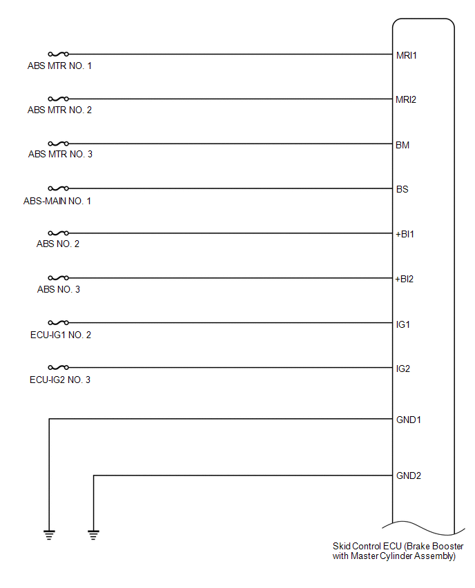
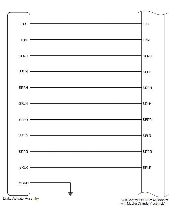
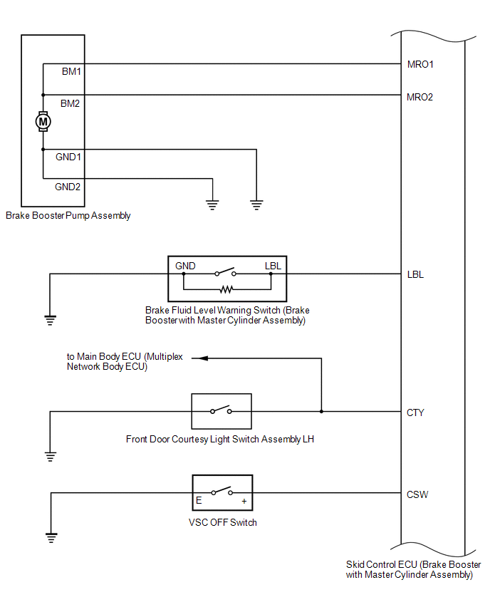
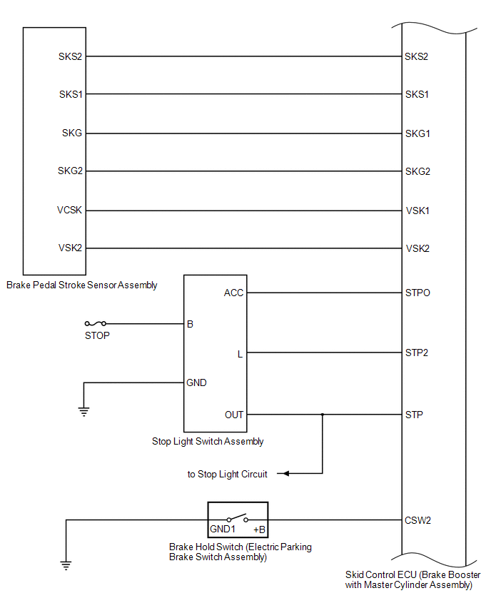
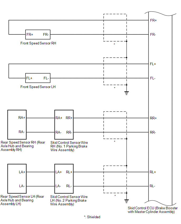
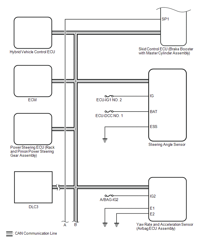
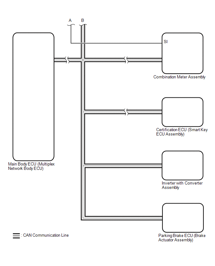
Terminals Of Ecu
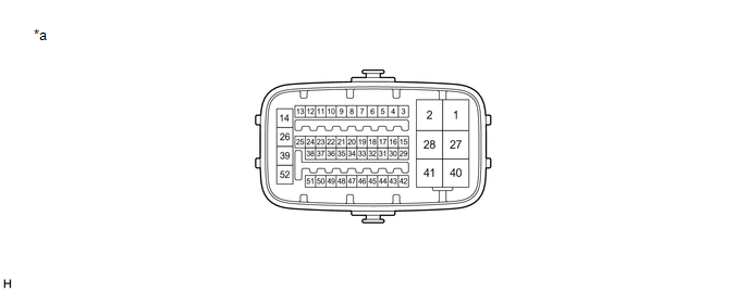
Toyota Avalon (XX50) 2019-2022 Owners Manual > Interior features: Other interior features
Other interior features Sun visors To set the visor in the forward position, flip it down. To set the visor in the side position, flip down, unhook, and swing it to the side. To use the side extender, place the visor in the side position, then slide it backward. Vanity mirrors Open the cover to use. ...