Motor Circuit (C1428)
DESCRIPTION
This DTC is
stored when the skid control ECU (brake actuator assembly) judges that
an abnormality occurred in the circuit used to operate the pump motor.
|
DTC No. | Detection Item |
DTC Detection Condition | Trouble Area |
|
C1428 | Motor Circuit |
A malfunction occurs in the pump motor circuit. |
Pump motor circuit |
WIRING DIAGRAM
Refer to DTC C146C.
Click here 
CAUTION / NOTICE / HINT
NOTICE:
- When replacing the skid control ECU (brake actuator assembly), perform
system variant learning and acceleration sensor zero point calibration.
Click here
- Inspect the fuses for circuits related to this system before performing the following procedure.
PROCEDURE
|
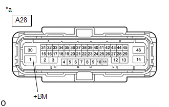
1. | CHECK HARNESS AND CONNECTOR (+BM TERMINAL) |
| (a) Make sure that there is no looseness at the locking part and the connecting part of the connector.
OK: The connector is securely connected. |
 |
|
*a | Front view of wire harness connector
(to Skid Control ECU (Brake Actuator Assembly)) | | |
(b) Disconnect the A28 skid control ECU (brake actuator assembly) connector.
(c) Check both the connector case and the terminals for deformation and corrosion.
OK:
No deformation or corrosion.
(d) Measure the voltage according to the value(s) in the table below.
Standard Voltage:
|
Tester Connection | Condition |
Specified Condition |
|
A28-1 (+BM) - Body ground |
Always | 11 to 14 V |
| NG |
 | REPAIR OR REPLACE HARNESS OR CONNECTOR (+BM CIRCUIT) |
|
OK |
 | |
| 2. |
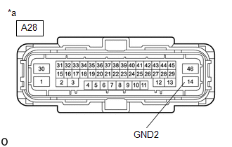
CHECK HARNESS AND CONNECTOR (GND2 TERMINAL) |
| (a) Measure the resistance according to the value(s) in the table below.
Standard Resistance: |
Tester Connection | Condition |
Specified Condition | |
A28-14 (GND2) - Body ground |
Always | Below 1 Ω | |
 |
|
*a | Front view of wire harness connector
(to Skid Control ECU (Brake Actuator Assembly)) | | |
| NG |
| REPAIR OR REPLACE HARNESS OR CONNECTOR (GND2 CIRCUIT) |
|
OK | |
| |
(a) Reconnect the A28 skid control ECU (brake actuator assembly) connector.
(b) Clear the DTCs.
Chassis > ABS/VSC/TRAC/EPB > Clear DTCs (c) Turn the engine switch off.
(d) Start the engine.
(e) Perform a road test.
(f) Check if the same DTC is output.
Chassis > ABS/VSC/TRAC/EPB > Trouble Codes
|
Result | Proceed to |
|
C1428 is not output | A |
|
C1428 is output | B |
| A |
| USE SIMULATION METHOD TO CHECK |
| B |
| REPLACE BRAKE ACTUATOR ASSEMBLY |
Steering Angle Sensor Power Source Voltage (C1432)
DESCRIPTION
This DTC is
stored when the skid control ECU (brake actuator assembly) receives a +B
line open signal from the steering angle sensor.
|
DTC No. | Detection Item |
DTC Detection Condition | Trouble Area |
|
C1432 | Steering Angle Sensor Power Source Voltage |
With
the +BS terminal voltage between 9.6 and 16.5 V, a steering angle
sensor power supply circuit malfunction signal is received from the
steering angle sensor. |
- Steering angle sensor power supply
- Steering angle sensor
|
WIRING DIAGRAM
Refer to DTC C1231.
Click here 
CAUTION / NOTICE / HINT
NOTICE:
Inspect the fuses for circuits related to this system before performing the following procedure.
PROCEDURE
| 1. |
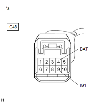
CHECK HARNESS AND CONNECTOR (POWER SOURCE TERMINAL) |
| (a) Remove the steering wheel and column cover. |
 |
|
*a | Front view of wire harness connector
(to Steering Angle Sensor) | | |
(b) Make sure that there is no looseness at the locking part and the connecting part of the connector.
OK:
The connector is securely connected.
(c) Disconnect the G48 steering angle sensor connector.
(d) Check both the connector case and the terminals for deformation and corrosion.
OK:
No deformation or corrosion.
(e) Measure the voltage according to the value(s) in the table below.
Standard Voltage:
|
Tester Connection | Condition |
Specified Condition |
|
G48-4 (BAT) - Body ground |
Always | 11 to 14 V |
|
G48-9 (IG1) - Body ground |
Engine switch on (IG) |
11 to 14 V |
| NG |
 | REPAIR OR REPLACE HARNESS OR CONNECTOR (POWER SOURCE CIRCUIT) |
|
OK |
 | |
| 2. |
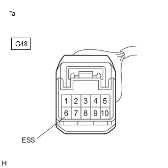
CHECK HARNESS AND CONNECTOR (GROUND TERMINAL) |
| (a) Turn the engine switch off. |
 |
|
*a | Front view of wire harness connector
(to Steering Angle Sensor) | | |
(b) Measure the resistance according to the value(s) in the table below.
NOTICE:
Before
measuring the resistance of the steering angle sensor, turn the engine
switch off and leave the vehicle for 1 minute or more without operating
the key or switches, or opening or closing the doors.
Standard Resistance:
|
Tester Connection | Condition |
Specified Condition |
|
G48-6 (ESS) - Body ground |
1 minute after engine switch off |
Below 1 Ω |
| OK |
| REPLACE STEERING ANGLE SENSOR |
| NG |
| REPAIR OR REPLACE HARNESS OR CONNECTOR (GROUND CIRCUIT) |


