Components
COMPONENTS
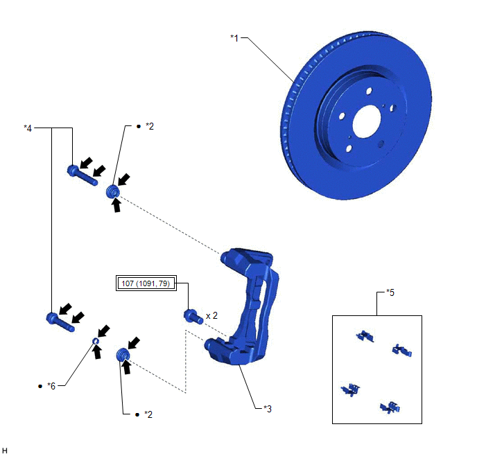
ILLUSTRATION
|
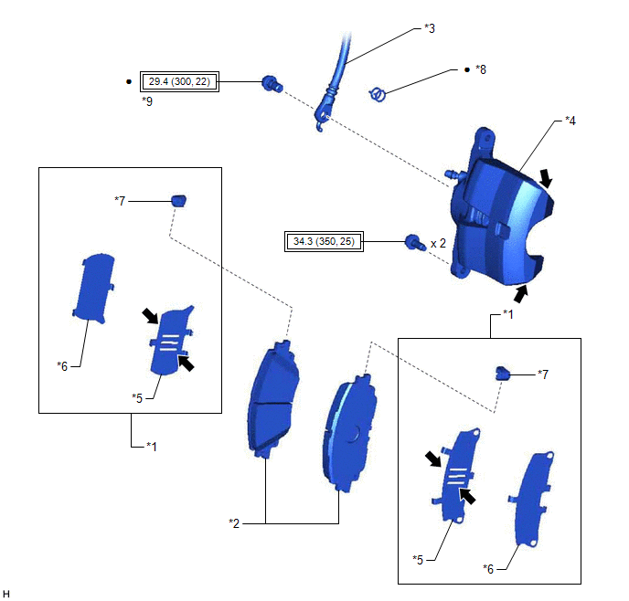
*1 | FRONT DISC BRAKE ANTI-SQUEAL SHIM KIT |
*2 | FRONT DISC BRAKE PAD |
|
*3 | FRONT FLEXIBLE HOSE |
*4 | FRONT DISC BRAKE CYLINDER ASSEMBLY |
|
*5 | FRONT NO. 1 DISC BRAKE ANTI-SQUEAL SHIM |
*6 | FRONT NO. 2 DISC BRAKE ANTI-SQUEAL SHIM |
|
*7 | FRONT DISC BRAKE PAD WEAR INDICATOR PLATE |
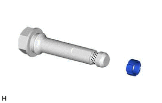
*8 | GASKET |
|
*9 | UNION BOLT |
- | - |
 |
Tightening torque for "Major areas involving basic vehicle performance such as moving/turning/stopping": N*m (kgf*cm, ft.*lbf) |
â—Ź | Non-reusable part |
 |
Disc brake grease | - |
- |
ILLUSTRATION
|
*1 | FRONT DISC |
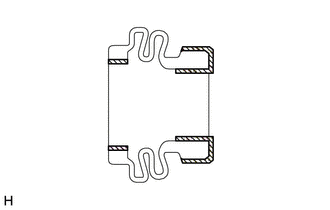
*2 | FRONT DISC BRAKE BUSHING DUST BOOT |
|
*3 | FRONT DISC BRAKE CYLINDER MOUNTING |
*4 | FRONT DISC BRAKE CYLINDER SLIDE PIN |
|
*5 | FRONT DISC BRAKE PAD SUPPORT PLATE |
*6 | FRONT DISC BRAKE CYLINDER SLIDE BUSHING |
|
|
Tightening torque for "Major areas involving basic vehicle performance such as moving/turning/stopping": N*m (kgf*cm, ft.*lbf) |
â—Ź | Non-reusable part |
|
|
Lithium soap base glycol grease |
- | - |
ILLUSTRATION
|
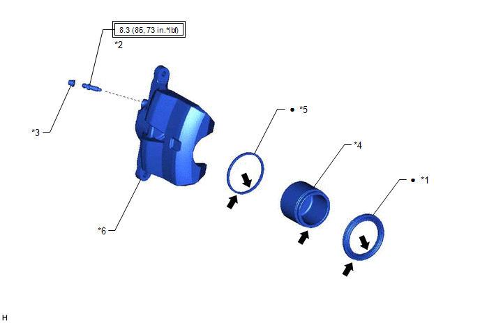
*1 | CYLINDER BOOT |
*2 | FRONT DISC BRAKE BLEEDER PLUG |
|
*3 | FRONT DISC BRAKE BLEEDER PLUG CAP |
*4 | FRONT DISC BRAKE PISTON |
|
*5 | PISTON SEAL |
*6 | FRONT DISC BRAKE CYLINDER |
|
|
Tightening torque for "Major areas involving basic vehicle performance such as moving/turning/stopping": N*m (kgf*cm, ft.*lbf) |
â—Ź | Non-reusable part |
|
|
Lithium soap base glycol grease |
- | - |
Disassembly
DISASSEMBLY
PROCEDURE
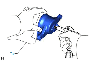
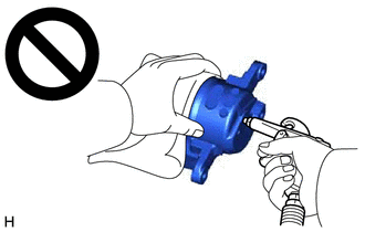
1. REMOVE FRONT DISC BRAKE PISTON
| (a) Place a piece of cloth between the front disc brake piston and front disc brake cylinder. |
|
(b) Apply compressed air to remove the front disc brake piston from the front disc brake cylinder.
CAUTION:
- Do not hold the front disc brake cylinder with any part of your hand
between the front disc brake cylinder and front disc brake piston.
- Do not place any part of your hand in front of the front disc brake
piston when using compressed air as a severe injury may result.
NOTICE:
Do not allow any brake fluid to spatter.
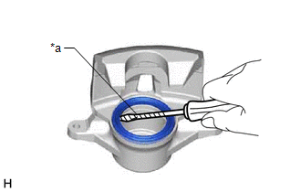
2. REMOVE CYLINDER BOOT
|
(a) Using a screwdriver with its tip wrapped with protective tape, remove the cylinder boot from the front disc brake cylinder.
NOTICE: Be careful not to damage the front disc brake cylinder. |
|
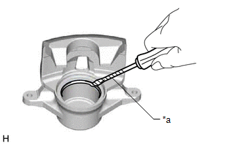
3. REMOVE PISTON SEAL
|
(a) Using a screwdriver with its tip wrapped with protective tape, remove the piston seal from the front disc brake cylinder.
NOTICE: Do not damage the inner surface or piston seal groove of the front disc brake cylinder. |
|
4. REMOVE FRONT DISC BRAKE BLEEDER PLUG CAP
(a) Remove the front disc brake bleeder plug cap from the front disc brake bleeder plug.
5. REMOVE FRONT DISC BRAKE BLEEDER PLUG
(a) Remove the front disc brake bleeder plug from the front disc brake cylinder.
Inspection
INSPECTION
PROCEDURE
1. INSPECT BRAKE CYLINDER AND PISTON
(a)
Check the front disc brake cylinder bore and front disc brake piston
for rust and scoring. If necessary, replace the front disc brake
cylinder assembly and front disc brake piston.
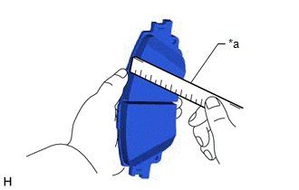
2. INSPECT PAD LINING THICKNESS
| (a) Using a ruler, measure the front disc brake pad lining thickness.
Standard Thickness: 11.0 mm (0.433 in.) Minimum Thickness:
1.0 mm (0.0394 in.)
HINT:
- If a front disc brake pad lining thickness is less than the minimum thickness, replace the front disc brake pads.
- Be sure to check front disc thickness when replacing the front disc brake pads with new ones.
| |
3. INSPECT FRONT DISC BRAKE PAD SUPPORT PLATE
(a)
Make sure that the front disc brake pad support plates have sufficient
rebound, no deformation, cracks or wear, and that all rust and dirt is
cleaned off. If necessary, replace the front disc brake pad support
plates.
4. INSPECT DISC THICKNESS
| (a) Using a micrometer, measure the front disc thickness. Standard Thickness:
28.0 mm (1.10 in.) Minimum Thickness: 25.0 mm (0.984 in.)
HINT: If the front disc thickness is less than the minimum thickness, replace the front disc. |
|
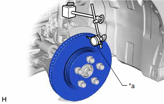
5. INSPECT DISC RUNOUT
(a) Inspect the front axle hub bearing looseness and front axle hub runout.
Click here 
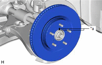
(b) Temporarily install the front disc with the 5 hub nuts.
Torque:
103 N·m {1050 kgf·cm, 76 ft·lbf}
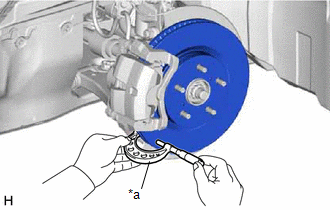
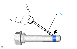
| (c) Using a dial indicator with magnetic base, measure the disc runout 10 mm (0.394 in.) from the outer edge of the front disc.
Maximum Disc Runout: 0.05 mm (0.00196 in.) NOTICE: Keep the magnet of the dial indicator away from the front speed sensor.
HINT: If
the runout exceeds the maximum value, change the installation position
of the front disc to minimize the runout. If the runout exceeds the
maximum even when the installation position is changed, grind the front
disc. If the front disc thickness is less than the minimum, replace the
front disc. |
 |
|
*a | Dial Indicator with Magnetic Base | | |
(d) Remove the 5 hub nuts and front disc.
Installation
INSTALLATION
CAUTION / NOTICE / HINT
NOTICE:
- Immediately after installing the brake pads, the braking performance may
be reduced. Always perform a road test in a safe place while paying
attention to the surroundings.
- After replacing the front disc brake pads, always perform a road test to check the braking performance and check for vibrations.
- When the brake pedal is first depressed after replacing the brake pads
or pushing back the disc brake piston, DTC C1214 may be stored. As there
is no malfunction, clear the DTC. (for HV Model)
- While the auxiliary battery is connected, even if the power switch is
off, the brake control system activates when the brake pedal is
depressed or any door courtesy switch turns on. Therefore, when
servicing the brake system components, do not operate the brake pedal or
open/close the doors while the auxiliary battery is connected. (for HV
Model)
HINT:
- Use the same procedure for the RH side and LH side.
- The following procedure is for the LH side.
PROCEDURE
1. INSTALL FRONT DISC
| (a) Align the matchmarks of the front disc and front axle hub sub-assembly, and install the front disc.
NOTICE: When replacing the front disc with a new one, select the installation position where the front disc has minimal runout. |
|
2. INSTALL FRONT DISC BRAKE CYLINDER MOUNTING
(a) Install the front disc brake cylinder mounting to the steering knuckle with the 2 bolts.
Torque:
107 N·m {1091 kgf·cm, 79 ft·lbf}
3. INSTALL FRONT DISC BRAKE BUSHING DUST BOOT
(a)
Apply a light layer of lithium soap base glycol grease to the entire
circumference of 2 new front disc brake bushing dust boots.
HINT:
Apply more than 0.3 g (0.01 oz) of lithium soap base glycol grease to each front disc brake bushing dust boot.
 |
Lithium Soap Base Glycol Grease |
(b) Install the 2 front disc brake bushing dust boots to the front disc brake cylinder mounting.
4. INSTALL FRONT DISC BRAKE CYLINDER SLIDE PIN
(a)
Apply a light layer of lithium soap base glycol grease to the contact
surface of the front disc brake cylinder slide pin (lower side).
|
| Lithium Soap Base Glycol Grease |
(b) Install a new front disc brake cylinder slide bushing to the front disc brake cylinder slide pin (lower side).
(c)
Apply a light layer of lithium soap base glycol grease to the sliding
part and the sealing surfaces of the 2 front disc brake cylinder slide
pins.
|
| Lithium Soap Base Glycol Grease |
(d) Install the 2 front disc brake cylinder slide pins to the front disc brake cylinder mounting.
(e) Push each front disc brake cylinder slide pin into the front disc brake bushing dust boot to engage the pin to the boot.
5. INSTALL FRONT DISC BRAKE PAD SUPPORT PLATE
(a) Install the 4 front disc brake pad support plates to the front disc brake cylinder mounting.
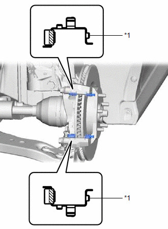
|
*1 | Front Disc Brake Pad Support Plate |
|
|
Identification Paint |
NOTICE:
Install the 2 front disc brake pad support plates with the identification paint is mounted on the inner side of the vehicle.
6. INSTALL FRONT DISC BRAKE ANTI-SQUEAL SHIM KIT
Click here

7. INSTALL FRONT DISC BRAKE PAD
(a) Install the 2 front disc brake pads to the front disc brake cylinder mounting.
NOTICE:
- Keep the friction surfaces of the front disc brake pads and front disc free from oil and grease.
- Install the front disc brake pad so that the pad wear indicator plate is mounted on the upper side of the vehicle.
8. INSTALL FRONT DISC BRAKE CYLINDER ASSEMBLY
(a)
Apply disc brake grease to the contact surfaces of the front disc brake
cylinder assembly and front disc brake pad as shown in the
illustration.
HINT:
Apply 0.3 g (0.01 oz) of disc brake grease to the front disc brake cylinder assembly.
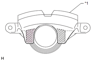
|
*1 | Front Disc Brake Cylinder Assembly |
|
|
Disc Brake Grease |
(b)
Hold each front disc brake cylinder slide pin and install the front
disc brake cylinder assembly to the front disc brake cylinder mounting
with the 2 bolts.
Torque:
34.3 N·m {350 kgf·cm, 25 ft·lbf}
9. CONNECT FRONT FLEXIBLE HOSE
(a) Connect the front flexible hose to the front disc brake cylinder assembly with a new union bolt and a new gasket.
Torque:
29.4 N·m {300 kgf·cm, 22 ft·lbf}
NOTICE:
Install the front flexible hose lock securely into the lock hole in the front disc brake cylinder assembly.
10. CONNECT CABLE TO NEGATIVE AUXILIARY BATTERY TERMINAL (for HV Model)
(a) Connect the reservoir level switch connector.
(b) Connect the cable to the negative (-) auxiliary battery terminal.
Click here
(c) Perform the following procedure if air bleeding is not necessary:
(1) Turn the power switch on (READY).
(2) Depress the brake pedal and release it.
(3) Clear the DTCs.
Click here
11. BLEED BRAKE LINE
for Gasoline Model: Click here
for HV Model: Click here
12. INSTALL FRONT WHEEL
Click here
Reassembly
REASSEMBLY
PROCEDURE
1. TEMPORARILY TIGHTEN FRONT DISC BRAKE BLEEDER PLUG
(a) Temporarily install the front disc brake bleeder plug to the front disc brake cylinder.
HINT:
Fully tighten the front disc brake bleeder plug after bleeding the system.
2. INSTALL FRONT DISC BRAKE BLEEDER PLUG CAP
(a) Install the front disc brake bleeder plug cap to the front disc brake bleeder plug.
3. INSTALL PISTON SEAL
(a) Apply a light layer of lithium soap base glycol grease to the entire circumference of a new piston seal.
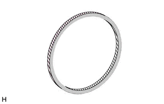
 |
Lithium Soap Base Glycol Grease |
| (b) Install the piston seal to the front disc brake cylinder.
NOTICE: Securely install the piston seal into the groove of the front disc brake cylinder. |
 |
|
*1 | Piston Seal | |
*2 | Front Disc Brake Cylinder | | |
4. INSTALL FRONT DISC BRAKE PISTON
(a) Apply a light layer of lithium soap base glycol grease to the entire circumference of a new cylinder boot.
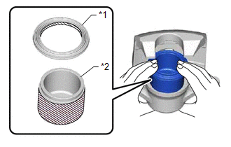
|
*1 | Cylinder Boot |
|
*2 | Front Disc Brake Piston |
|
|
Lithium Soap Base Glycol Grease |
(b) Apply a light layer of lithium soap base glycol grease to the contact surfaces of the front disc brake piston.
(c) Install the cylinder boot to the front disc brake piston.
NOTICE:
Securely install the cylinder boot into the groove of the front disc brake piston.
(d) Install the front disc brake piston to the front disc brake cylinder.
NOTICE:
Do not forcibly install the front disc brake piston into the front disc brake cylinder.
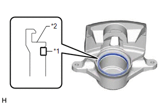
5. INSTALL CYLINDER BOOT
|
(a) Install the cylinder boot to the front disc brake cylinder as shown in the illustration.
NOTICE:
- Securely install the cylinder boot into the groove of the front disc brake cylinder and front disc brake piston.
- Do not damage the cylinder boot.
|
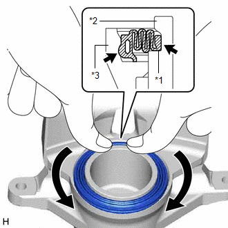 |
|
*1 | Cylinder Boot | |
*2 | Front Disc Brake Piston | |
*3 | Front Disc Brake Cylinder | | |
Removal
REMOVAL
CAUTION / NOTICE / HINT
The
necessary procedures (adjustment, calibration, initialization, or
registration) that must be performed after parts are removed and
installed, or replaced during front brake removal/installation are shown
below.
Necessary Procedures After Parts Removed/Installed/Replaced |
Replaced Part or Performed Procedure |
Necessary Procedure | Effect/Inoperative Function when Necessary Procedure not Performed |
Link |
|
*1: for HV Model
*2: When performing learning using the Techstream. Click here
 |
|
Auxiliary battery terminal is disconnected/reconnected*1 |
Perform steering sensor zero point calibration |
Lane departure alert system (w/ Steering Control) |
|
|
Pre-collision system |
| Intelligent clearance sonar system*2 |
|
Lighting system (w/ AFS)(EXT) |
|
Memorize steering angle neutral point |
Parking assist monitor system |
|
|
Panoramic view monitor system |
|
NOTICE:
- Immediately after installing the brake pads, the braking performance may
be reduced. Always perform a road test in a safe place while paying
attention to the surroundings.
- After replacing the front disc brake pads, always perform a road test to check the braking performance and check for vibrations.
- When the brake pedal is first depressed after replacing the brake pads
or pushing back the disc brake piston, DTC C1214 may be stored. As there
is no malfunction, clear the DTC. (for HV Model)
- While the auxiliary battery is connected, even if the power switch is
off, the brake control system activates when the brake pedal is
depressed or any door courtesy switch turns on. Therefore, when
servicing the brake system components, do not operate the brake pedal or
open/close the doors while the auxiliary battery is connected. (for HV
Model)
HINT:
- Use the same procedure for the RH side and LH side.
- The following procedure is for the LH side.
PROCEDURE
1. PRECAUTION (for HV Model)
NOTICE:
After
turning the power switch off, waiting time may be required before
disconnecting the cable from the negative (-) auxiliary battery
terminal. Therefore, make sure to read the disconnecting the cable from
the negative (-) auxiliary battery terminal notices before proceeding
with work.
Click here
2. DISABLE BRAKE CONTROL (for HV Model)
(a) Wait at least 2 minutes after turning the power switch off.
NOTICE:
When
the brake pedal is depressed or the door courtesy switch is turned on
even if the power switch is off, the brake control system activates.
Therefore do not depress the brake pedal or open/close the doors until
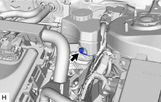
the reservoir level switch connector is disconnected.
| (b) Disconnect the reservoir level switch connector. | |
(c) Disconnect the cable from the negative (-) auxiliary battery terminal.
Click here
(d) Depress the brake pedal 40 times or more to return all the fluid in the accumulator back to the reservoir.
(e) Check that the brake pedal cannot be further depressed.
3. REMOVE FRONT WHEEL
Click here
4. DRAIN BRAKE FLUID
NOTICE:
If brake fluid leaks onto any painted surface, immediately wash it off.
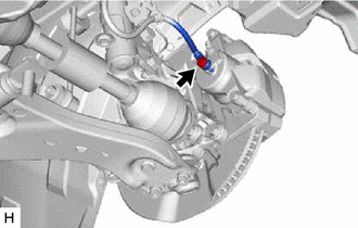
5. DISCONNECT FRONT FLEXIBLE HOSE
| (a) Remove the union bolt and gasket, and disconnect the front flexible hose from the front disc brake cylinder assembly. |
|
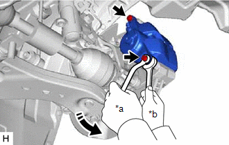
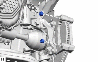
6. REMOVE FRONT DISC BRAKE CYLINDER ASSEMBLY
| (a) Hold the 2 front disc brake cylinder slide pins and remove the 2 bolts and front disc brake cylinder assembly. |
|
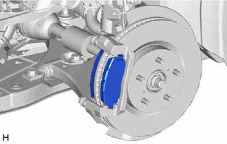
7. REMOVE FRONT DISC BRAKE PAD
| (a) Remove the 2 front disc brake pads from the front disc brake cylinder mounting. |
|
8. REMOVE FRONT DISC BRAKE ANTI-SQUEAL SHIM KIT
Click here
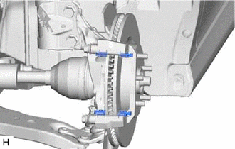
9. REMOVE FRONT DISC BRAKE PAD SUPPORT PLATE
| (a) Remove the 4 front disc brake pad support plates from the front disc brake cylinder mounting. |
|
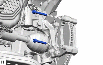
10. REMOVE FRONT DISC BRAKE CYLINDER SLIDE PIN
| (a) Remove the 2 front disc brake cylinder slide pins from the front disc brake cylinder mounting. |
|
| (b)
Using a screwdriver with its tip wrapped with protective tape, remove
the front disc brake cylinder slide bushing from the front disc brake
cylinder slide pin (lower side). NOTICE: Do not damage the front disc brake cylinder slide pin. |
|
11. REMOVE FRONT DISC BRAKE BUSHING DUST BOOT
| (a) Remove the 2 front disc brake bushing dust boots from the front disc brake cylinder mounting. |
|
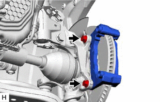
12. REMOVE FRONT DISC BRAKE CYLINDER MOUNTING
| (a) Remove the 2 bolts and front disc brake cylinder mounting from the steering knuckle. |
|
13. REMOVE FRONT DISC
|
(a) Put matchmarks on the front disc and the front axle hub sub-assembly. |
|
(b) Remove the front disc.