Dtc Check / Clear
DTC CHECK / CLEAR
HINT:
- DTCs which are stored in the skid control ECU (brake booster with master
cylinder assembly) can be displayed on the Techstream. The Techstream
can display the current, pending and permanent DTCs.
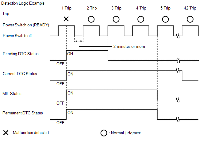
- If a malfunction is detected during the current driving cycle, current and permanent DTCs are stored.
- Current DTCs can be cleared by using the Techstream. However, permanent
DTCs cannot be cleared using either of these two methods.
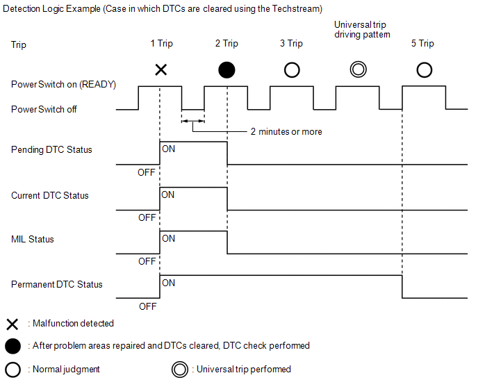
- After clearing current DTCs using the Techstream, permanent DTCs can be
cleared when the system is determined to be normal for the relevant DTCs
and then the universal trip is performed. The driving pattern to obtain
a normal judgment is described under the "Confirmation Driving Pattern"
for the respective DTC.
Detection Logic Examples |
Pending DTC | Store condition |
Malfunction detected |
|
Clear condition | Power switch turned on (IG) after normal judgment obtained in 1 driving cycle
or DTCs cleared using Techstream |
|
Current DTC | Store condition |
Malfunction detected |
| Clear condition |
No malfunctions in 40 driving cycles or DTCs cleared using Techstream |
|
Permanent DTC | Store condition |
Malfunction detected |
| Clear condition |
Power switch turned on (IG) after normal judgment obtained in 3 consecutive driving cycles
or After DTCs cleared using Techstream, normal judgment obtained and universal trip performed |
|
MIL | ON | Malfunction detected |
|
OFF | Power switch turned on (IG) after normal judgment obtained in 3 consecutive driving cycles
or DTCs cleared using Techstream |


HINT:
- Obtaining a normal judgment and performing a universal trip driving
pattern can be done in the same driving cycle or in different driving
cycles.
- Ensure to wait at least 2 minutes between each trip.
CHECK DTC
(a) Connect the Techstream to the DLC3.
(b) Turn the power switch on (IG).
(c) Turn the Techstream on.
(d) Enter the following menus: Chassis / ABS/VSC/TRAC / Trouble Codes.
Chassis > ABS/VSC/TRAC > Trouble Codes
(e) Check the DTC(s) and freeze frame data, and then write them down.
(f) Check the details of the DTC(s).
Click here 
CLEAR DTC (PENDING AND CURRENT DTC)
(a) Connect the Techstream to the DLC3.
(b) Turn the power switch on (IG).
(c) Turn the Techstream on.
(d) Enter the following menus: Chassis / ABS/VSC/TRAC / Trouble Codes.
(e) Clear the DTCs.
Chassis > ABS/VSC/TRAC > Clear DTCs CLEAR PERMANENT DTC
HINT:
Even
if the following procedure is not performed, permanent DTCs are cleared
by obtaining a normal judgment during 3 consecutive driving cycles.

(a) Connect the Techstream to the DLC3.
(b) Turn the power switch on (IG).
(c) Turn the Techstream on.
(d) Enter the following menus: Chassis / ABS/VSC/TRAC / Trouble Codes.
Chassis > ABS/VSC/TRAC > Trouble Codes
HINT:
If "PERMANENT" in the top right of the screen displays "YES", permanent DTCs are stored.
(e) Change the tab from "Enhanced" to "Generic".
(f) Check if permanent DTCs are stored.
HINT:
If permanent DTCs are not output, it is not necessary to continue this procedure.
(g) Clear the DTCs.
Chassis > ABS/VSC/TRAC > Clear DTCs (h) Perform the respective confirmation driving patterns in order to obtain a normal judgment for the output DTCs.
HINT:
For the confirmation driving pattern, refer to the procedures for the relevant DTC.
Click here 
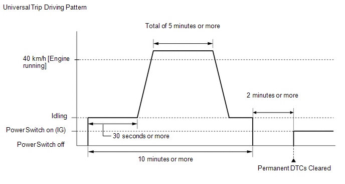
(i) Perform the universal trip.
CAUTION:
When performing a driving pattern, obey all speed limits and traffic laws.
- Put the engine in Inspection Mode (Maintenance Mode).
Click here 
- Start the engine.
- Idle the engine for 30 seconds or more.
- With the engine running, drive the vehicle at 40 km/h (25 mph) or more for a total of 5 minutes or more.
HINT:
- It is possible to complete the drive pattern even if the vehicle
decelerates to less than 40 km/h (25 mph) during the driving cycle
provided that the vehicle is driven at 40 km/h (25 mph) or more for a
total of 5 minutes.
- If the engine stops, further depress the accelerator pedal to restart the engine.
- Allow 10 minutes or more to elapse from the time the engine is started.
(j) Turn the power switch off.
(k) Wait 2 minutes or more.
(l) Turn the power switch on (IG).
(m) Enter the following menus: Chassis / ABS/VSC/TRAC / Trouble Codes.
(n) Check that the permanent DTCs have been cleared.
Chassis > ABS/VSC/TRAC > Trouble Codes
HINT:
The permanent DTCs are cleared when the universal trip is completed.
Excessive Brake Pedal Travel (No Fluid Leaks and No Air in System)
DESCRIPTION
Depending on
the malfunction, the skid control ECU (brake booster with master
cylinder assembly) prohibits operation of the electronically controlled
brake system to protect components and prevent incorrect operation when
DTCs are stored.
If the switching solenoid is
disabled due to prohibition of the electronically controlled brake
system, the response of the brake pedal changes and braking performance
is reduced.
CAUTION / NOTICE / HINT
NOTICE:
After
replacing the skid control ECU (brake booster with master cylinder
assembly), perform linear solenoid valve offset learning, ABS holding
solenoid valve learning, yaw rate and acceleration sensor zero point
calibration and system information memorization after performing "Reset
Memory".
Click here 
PROCEDURE
(a) Check the conditions at the time the problem occurred.
(1) Whether a warning light illuminated or the buzzer sounded.
(2) Road surface condition when the problem occurred and just before the problem occurred.
(3) When the problem occurred and how many times the brake pedal was depressed before the problem occurred.
(4) Frequency of the abnormal brake pedal response.
|
NEXT |
 | |
| 2. |
CHECK DTC AND FREEZE FRAME DATA |
(a) Using the Techstream, check DTCs and Freeze Frame Data.
Click here 
Chassis > ABS/VSC/TRAC > Trouble Codes
| Result |
Proceed to |
| DTCs are not output. |
A |
| DTCs are output. |
B |
HINT:
- If there are currently no warnings and the brake pedal travel is not
excessive, DTCs may have been cleared after the system returned to
normal.
- If the brake pedal response returned to normal and there are currently no warnings, the system is normal.
| B |
 | REPAIR CIRCUITS INDICATED BY OUTPUT DTCS |
|
A |
 | |
(a)
While depressing the brake pedal by hand, check the installation
condition of the brake pedal stroke sensor assembly and brake pedal, and
check for mechanical malfunctions.
(b) Check and adjust the brake pedal height.
Click here 
|
NEXT |
 | |
| 4. |
INSPECT BRAKE BOOSTER WITH MASTER CYLINDER ASSEMBLY |
(a) Check the brake booster with master cylinder assembly.
Click here

OK:
The brake booster with master cylinder assembly is normal.
| OK |
 | USE SIMULATION METHOD TO CHECK |
| NG |
 | REPLACE BRAKE BOOSTER WITH MASTER CYLINDER ASSEMBLY |
Fail-safe Chart
FAIL-SAFE CHART
FAIL-SAFE FUNCTION OF CONTROL SYSTEM
(a)
When a malfunction is detected in the brake control system, the skid
control ECU (brake booster with master cylinder assembly) turns the ABS
warning, brake warning / red (malfunction), brake warning / yellow
(minor malfunction) and slip indicator lights on, flashes the brake hold
operated indicator light*, as well as prohibits ABS, BA, TRAC, VSC,
secondary collision brake and brake hold operation.
- *: The brake hold switch (electric parking brake switch assembly) is turned on under the following vehicle conditions.
- Vehicle Conditions:
- The driver side door is closed.
- The driver side seat belt is fastened.
(b)
If the skid control ECU (brake booster with master cylinder assembly)
detects that a system related to the hybrid control system is
malfunctioning, it will prohibit operation of the TRAC and VSC systems
in order to prevent further malfunctions and to protect the systems.
(c)
Brake hold control prohibits brake hold operation in order to protect
the system and prevent improper operation when the electronically
controlled brake system, electric parking brake system or hybrid control
system is malfunctioning.
(d) If the skid control
ECU (brake booster with master cylinder assembly) detects that a system
related to the airbag system is malfunctioning, it will prohibit
operation of the secondary collision brake in order to prevent further
malfunctions and to protect the systems.
|
Item | Operation |
|
Malfunction in the ABS. | ABS, BA, TRAC and VSC control prohibited.
Brake hold control prohibited.* |
|
Malfunction in the BA system. | ABS, BA, TRAC and VSC control prohibited.
Brake hold control prohibited.* |
|
Malfunction in the EBD system. | ABS, EBD, BA, TRAC and VSC control prohibited.
Brake hold control prohibited.* |
|
Malfunction in the TRAC system. | ABS, BA, TRAC and VSC control prohibited.
Brake hold control prohibited.* |
|
Malfunction in the VSC system. | ABS, BA, TRAC and VSC control prohibited.
Brake hold control prohibited.* |
- *: Only during brake hold control
FAIL-SAFE FUNCTION OF HYDRAULIC SYSTEM
(a)
If a malfunction is detected in the skid control ECU (brake booster
with master cylinder assembly), brake actuator (brake booster with
master cylinder assembly) or an individual sensor, control will be
stopped and brake effort will be generated by the hydraulic brake
booster (brake booster with master cylinder assembly).
(b)
If brake control is stopped due to a malfunction in the hydraulic
pressure source, the pressure generated in the master cylinder by the
driver is applied to the wheel cylinders to ensure braking force.
|
Item | Operation |
|
Skid control ECU (Brake booster with master cylinder assembly) malfunction. |
Hydraulic brake booster (brake booster with master cylinder assembly) generates braking force. |
|
Hydraulic pressure controlling components malfunction. |
Hydraulic brake booster (brake booster with master cylinder assembly) generates braking force. |
|
Power supply components (Hydraulic pressure source) malfunction. |
Braking force solely generated by the driver. |


