DESCRIPTION
Refer to DTCs C1415 and C1416.
Click here

|
DTC No. | Detection Item |
INF Code | DTC Detection Condition |
Trouble Area | MIL |
Note |
|---|---|---|---|---|---|---|
| C1407 |
Open or Short in Rear Speed Sensor RH Circuit |
523 526 528 |
|
| Comes on |
|
| C1408 |
Open or Short in Rear Speed Sensor LH Circuit |
533 536 538 |
|
| Comes on |
|
MONITOR DESCRIPTION
The skid control ECU (brake booster with master cylinder assembly) monitors the output voltage and power supply voltage of the speed sensors. If the output voltage of the speed sensor is outside the normal range, or if the voltage at VM1 of the skid control ECU (brake booster with master cylinder assembly) is normal and the power supply voltage of the speed sensor drops below a specific value, the skid control ECU (brake booster with master cylinder assembly) judges that the circuit of the speed sensor is malfunctioning and illuminates the MIL and stores a DTC.
MONITOR STRATEGY
|
Related DTCs | C050E: Speed sensor circuit low C050F: Speed sensor circuit high C0514: Speed sensor circuit low C0515: Speed sensor circuit high C14E7 (Case 1): Speed sensor voltage circuit low C14E7 (Case 2): Speed sensor voltage circuit low C14EA (Case 1): Speed sensor voltage circuit low C14EA (Case 2): Speed sensor voltage circuit low |
|
Required Sensors/Components(Main) | Speed sensor Skid control ECU (brake booster with master cylinder assembly) |
|
Required Sensors/Components(Related) | Speed sensor Skid control ECU (brake booster with master cylinder assembly) |
|
Frequency of Operation | Continuous |
|
Duration | 0.5 seconds: C050E, C050F, C0514, C0515, C14E7 (Case 1) and C14EA (Case 1) 60 seconds: C14E7 (Case 2) and C14EA (Case 2) |
|
MIL Operation | Immediately |
|
Sequence of Operation | None |
TYPICAL ENABLING CONDITIONS
C050E, C050F, C0514 and C0515|
Monitor runs whenever the following DTCs are not stored |
C14E1, C14E4, C14E7, C14EA(Case 1) (Speed sensor voltage circuit low) C14E1, C14E4, C14E7, C14EA(Case 2) (Speed sensor voltage circuit low) |
|
All of the following conditions are met | - |
|
Brake system voltage 1 (VM1) | Higher than 7.54 V |
|
Serial communication with low side IC | Valid |
|
Command to speed sensor power supply |
On |
| Speed sensor fail (C14E1, C14E4, C14E7, C14EA) |
Not detected |
|
Monitor runs whenever the following DTCs are not stored |
C0502, C0508, C050E, C0514 (Speed sensor circuit low) C0503, C0509, C050F, C0515 (Speed sensor circuit high) C14E1, C14E4, C14E7, C14EA (Case 2) (Speed sensor voltage circuit low) |
|
All of the following conditions are met | - |
|
Brake system voltage 1 (VM1) | Higher than 7.54 V |
|
Serial communication with low side IC | Valid |
|
Command to speed sensor power supply |
On |
| Speed sensor fail (C0502, C0503, C0508, C0509, C050E, C050F, C0514, C0515, C14E1 (Case 2), C14E4 (Case 2), C14E7 (Case 2), C14EA (Case 2)) |
Not detected |
|
Monitor runs whenever the following DTCs are not stored |
C0502, C0508, C050E, C0514 (Speed sensor circuit low) C0503, C0509, C050F, C0515 (Speed sensor circuit high) C14E1, C14E4, C14E7, C14EA (Case 1) (Speed sensor voltage circuit low) |
|
All of the following conditions are met | - |
|
Brake system voltage 1 (VM1) | Higher than 7.54 V |
|
Serial communication with low side IC | Valid |
|
Command to speed sensor power supply |
On |
| Speed sensor fail (C0502, C0503, C0508, C0509, C050E, C050F, C0514, C0515, C14E1 (Case 1), C14E4 (Case 1), C14E7 (Case 1), C14EA (Case 1)) |
Not detected |
TYPICAL MALFUNCTION THRESHOLDS
C050E and C0514|
Speed sensor voltage | Less than 0.4 V |
|
Speed sensor voltage | Higher than 3.3 V |
|
Speed sensor power supply voltage | Less than 6.1 V |
|
The speed sensor power supply voltage drops below 6.1 V for 0.2 seconds or more |
Met |
COMPONENT OPERATING RANGE
C050E, C050F, C0514 and C0515|
Both of the following conditions are met |
- |
| Serial communication with low side IC |
Valid |
| Speed sensor voltage |
0.4 V or more, and 3.3 V or less |
|
Both of the following conditions are met |
- |
| Serial communication with low side IC |
Valid |
| Speed sensor power supply voltage |
6.1 V or more |
|
All of the following conditions are met |
- |
| Brake system voltage 1 (VM1) |
Higher than 7.54 V |
|
Serial communication with low side IC |
Valid |
| Command to speed sensor power supply |
On |
| Speed sensor fail (C0502, C0503, C0508, C0509, C050E, C050F, C0514, C0515, C14E1 (Case 1), C14E4 (Case 1), C14E7 (Case 1), C14EA (Case 1)) |
Not detected |
| The speed sensor power supply voltage drops below 6.1 V for 0.2 seconds or more |
Not met |
CONFIRMATION DRIVING PATTERN
HINT:
Click here
HINT:
WIRING DIAGRAM
Refer to DTCs C1415 and C1416.
Click here
CAUTION / NOTICE / HINT
NOTICE:
Click here
PROCEDURE
|
1. | CHECK DTC |
(a) Clear the DTCs.
Click here
(b) Turn the power switch off.
(c) Turn the power switch on (IG).
(d) Check if the same DTC is output.
Click here
| Result |
Proceed to |
|---|---|
| DTC C1407 is output. |
A |
| DTC C1408 is output. |
B |
| B |
 | GO TO STEP 8 |
|
| 2. |
READ VALUE USING TECHSTREAM (MOMENTARY INTERRUPTION) |
(a) Using the Techstream, check for any momentary interruptions in the wire harness and connector corresponding to a DTC.
Click here
|
Tester Display | Measurement Item |
Range | Normal Condition |
Diagnostic Note |
|---|---|---|---|---|
|
RR Speed Open | Rear speed sensor RH open detection |
Error or Normal | Error: Momentary interruption Normal: Normal | - |
|
Tester Display |
|---|
| RR Speed Open |
(b) Check for any momentary interruptions in the wire harness and connectors.
OK:
There are no momentary interruptions.
NOTICE:
Perform the above inspection before removing the sensor and connector.
| NG | | GO TO STEP 5 |
|
| 3. |
READ VALUE USING TECHSTREAM (REAR SPEED SENSOR RH) |
(a) Select the Data List on the Techstream.
Click here
|
Tester Display | Measurement Item |
Range | Normal Condition |
Diagnostic Note |
|---|---|---|---|---|
|
RR Wheel Speed | Rear speed sensor RH |
Min.: 0 km/h (0 mph), Max.: 326.4 km/h (203 mph) |
Vehicle stopped: 0 km/h (0 mph) |
When driving at constant speed: No large fluctuations |
|
Tester Display |
|---|
| RR Wheel Speed |
(b) Check the rear speed sensor RH output value.
OK:
The output value changes in accordance with the vehicle speed.
| NG | | GO TO STEP 5 |
|
| 4. |
RECONFIRM DTC |
(a) Clear the DTCs.
Click here
(b) Turn the power switch off.
(c) Turn the power switch on (READY).
(d) Perform a road test.
(e) Check if the same DTC is output.
Click here
| Result |
Proceed to |
|---|---|
| DTC C1407 is not output. |
A |
| DTC C1407 is output. |
B |
| A |
| USE SIMULATION METHOD TO CHECK |
| B |
| REPLACE BRAKE BOOSTER WITH MASTER CYLINDER ASSEMBLY |
| 5. |
INSPECT NO. 1 PARKING BRAKE WIRE ASSEMBLY |
| (a) Turn the power switch off. |
|
(b) Make sure that there is no looseness at the locking part and the connecting part of the connectors.
OK:
The connector is securely connected.
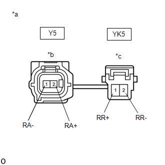
(c) Disconnect the Y5 and YK5 skid control sensor wire RH (No. 1 parking brake wire assembly) connectors.
(d) Check both the connector case and the terminals for deformation and corrosion.
OK:
No deformation or corrosion.
(e) Measure the resistance according to the value(s) in the table below.
Standard Resistance:
|
Tester Connection | Condition |
Specified Condition |
|---|---|---|
|
Y5-2 (RA+) - YK5-1 (RR+) |
Always | Below 1 Ω |
|
Y5-2 (RA+) or YK5-1 (RR+) - Body ground and other terminals |
Always | 10 kΩ or higher |
|
Y5-1 (RA-) - YK5-2 (RR-) |
Always | Below 1 Ω |
|
Y5-1 (RA-) or YK5-2 (RR-) - Body ground and other terminals |
Always | 10 kΩ or higher |
| NG | | REPLACE NO. 1 PARKING BRAKE WIRE ASSEMBLY |
|
| 6. |
CHECK HARNESS AND CONNECTOR (BRAKE BOOSTER WITH MASTER CYLINDER ASSEMBLY - NO. 1 PARKING BRAKE WIRE ASSEMBLY) |
(a) Make sure that there is no looseness at the locking part and the connecting part of the connector.
OK:
The connector is securely connected.
(b) Disconnect the A35 skid control ECU (brake booster with master cylinder assembly) connector.
(c) Check both the connector case and the terminals for deformation and corrosion.
OK:
No deformation or corrosion.
(d) Measure the resistance according to the value(s) in the table below.
Standard Resistance:
|
Tester Connection | Condition |
Specified Condition |
|---|---|---|
|
A35-7 (RR+) - YK5-1 (RR+) |
Always | Below 1 Ω |
|
A35-7 (RR+) or YK5-1 (RR+) - Body ground |
Always | 10 kΩ or higher |
|
A35-8 (RR-) - YK5-2 (RR-) |
Always | Below 1 Ω |
|
A35-8 (RR-) or YK5-2 (RR-) - Body ground |
Always | 10 kΩ or higher |
| NG | | REPAIR OR REPLACE HARNESS OR CONNECTOR |
|
| 7. |
INSPECT BRAKE BOOSTER WITH MASTER CYLINDER ASSEMBLY (SENSOR OUTPUT) |
| (a) Reconnect the A35 skid control ECU (brake booster with master cylinder assembly) connector. |
|
(b) Turn the power switch on (IG).
(c) Measure the voltage according to the value(s) in the table below.
Standard Voltage:
|
Tester Connection | Condition |
Specified Condition |
|---|---|---|
|
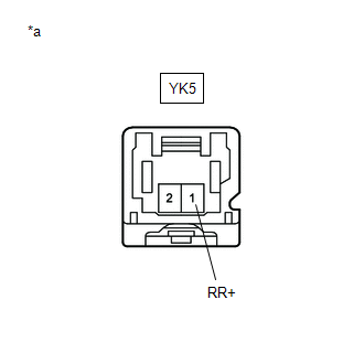
YK5-1 (RR+) - Body ground |
Power switch on (IG) |
8 to 14 V |
NOTICE:
Check the rear speed sensor RH signal after replacement.
Click here
HINT:
The rear speed sensor RH and rear speed sensor rotor RH are incorporated into the rear axle hub and bearing assembly RH.
If the rear speed sensor RH and rear speed sensor rotor RH need to be replaced, replace the rear axle hub and bearing assembly RH.
| OK | | REPLACE REAR AXLE HUB AND BEARING ASSEMBLY RH |
| NG | | REPLACE BRAKE BOOSTER WITH MASTER CYLINDER ASSEMBLY |
| 8. |
READ VALUE USING TECHSTREAM (MOMENTARY INTERRUPTION) |
(a) Using the Techstream, check for any momentary interruptions in the wire harness and connector corresponding to a DTC.
Click here
|
Tester Display | Measurement Item |
Range | Normal Condition |
Diagnostic Note |
|---|---|---|---|---|
|
RL Speed Open | Rear speed sensor LH open detection |
Error or Normal | Error: Momentary interruption Normal: Normal | - |
|
Tester Display |
|---|
| RL Speed Open |
(b) Check for any momentary interruptions in the wire harness and connectors.
OK:
There are no momentary interruptions.
NOTICE:
Perform the above inspection before removing the sensor and connector.
| NG | | GO TO STEP 11 |
|
| 9. |
READ VALUE USING TECHSTREAM (REAR SPEED SENSOR LH) |
(a) Select the Data List on the Techstream.
Click here
|
Tester Display | Measurement Item |
Range | Normal Condition |
Diagnostic Note |
|---|---|---|---|---|
|
RL Wheel Speed | Rear speed sensor LH |
Min.: 0 km/h (0 mph), Max.: 326.4 km/h (203 mph) |
Vehicle stopped: 0 km/h (0 mph) |
When driving at constant speed: No large fluctuations |
|
Tester Display |
|---|
| RL Wheel Speed |
(b) Check the rear speed sensor LH output value.
OK:
The output value changes in accordance with the vehicle speed.
| NG | | GO TO STEP 11 |
|
| 10. |
RECONFIRM DTC |
(a) Clear the DTCs.
Click here
(b) Turn the power switch off.
(c) Turn the power switch on (READY).
(d) Perform a road test.
(e) Check if the same DTC is output.
Click here
| Result |
Proceed to |
|---|---|
| DTC C1408 is not output. |
A |
| DTC C1408 is output. |
B |
| A |
| USE SIMULATION METHOD TO CHECK |
| B |
| REPLACE BRAKE BOOSTER WITH MASTER CYLINDER ASSEMBLY |
| 11. |
INSPECT NO. 2 PARKING BRAKE WIRE ASSEMBLY |
| (a) Turn the power switch off. |
|
(b) Make sure that there is no looseness at the locking part and the connecting part of the connectors.
OK:
The connector is securely connected.
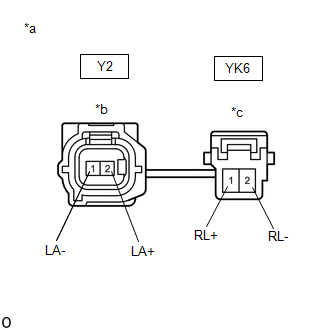
(c) Disconnect the Y2 and YK6 skid control sensor wire LH (No. 2 parking brake wire assembly) connectors.
(d) Check both the connector case and the terminals for deformation and corrosion.
OK:
No deformation or corrosion.
(e) Measure the resistance according to the value(s) in the table below.
Standard Resistance:
|
Tester Connection | Condition |
Specified Condition |
|---|---|---|
|
Y2-2 (LA+) - YK6-1 (RL+) |
Always | Below 1 Ω |
|
Y2-2 (LA+) or YK6-1 (RL+) - Body ground and other terminals |
Always | 10 kΩ or higher |
|
Y2-1 (LA-) - YK6-2 (RL-) |
Always | Below 1 Ω |
|
Y2-1 (LA-) or YK6-2 (RL-) - Body ground and other terminals |
Always | 10 kΩ or higher |
| NG | | REPLACE NO. 2 PARKING BRAKE WIRE ASSEMBLY |
|
| 12. |
CHECK HARNESS AND CONNECTOR (BRAKE BOOSTER WITH MASTER CYLINDER ASSEMBLY - NO. 2 PARKING BRAKE WIRE ASSEMBLY) |
(a) Make sure that there is no looseness at the locking part and the connecting part of the connector.
OK:
The connector is securely connected.
(b) Disconnect the A35 skid control ECU (brake booster with master cylinder assembly) connector.
(c) Check both the connector case and the terminals for deformation and corrosion.
OK:
No deformation or corrosion.
(d) Measure the resistance according to the value(s) in the table below.
Standard Resistance:
|
Tester Connection | Condition |
Specified Condition |
|---|---|---|
|
A35-34 (RL+) - YK6-1 (RL+) |
Always | Below 1 Ω |
|
A35-34 (RL+) or YK6-1 (RL+) - Body ground |
Always | 10 kΩ or higher |
|
A35-35 (RL-) - YK6-2 (RL-) |
Always | Below 1 Ω |
|
A35-35 (RL-) or YK6-2 (RL-) - Body ground |
Always | 10 kΩ or higher |
| NG | | REPAIR OR REPLACE HARNESS OR CONNECTOR |
|
| 13. |
INSPECT BRAKE BOOSTER WITH MASTER CYLINDER ASSEMBLY (SENSOR OUTPUT) |
| (a) Reconnect the A35 skid control ECU (brake booster with master cylinder assembly) connector. |
|
(b) Turn the power switch on (IG).
(c) Measure the voltage according to the value(s) in the table below.
Standard Voltage:
|
Tester Connection | Condition |
Specified Condition |
|---|---|---|
|
YK6-1 (RL+) - Body ground |
Power switch on (IG) |
8 to 14 V |
NOTICE:
Check the rear speed sensor LH signal after replacement.
Click here
HINT:
The rear speed sensor LH and rear speed sensor rotor LH are incorporated into the rear axle hub and bearing assembly LH.
If the rear speed sensor LH and rear speed sensor rotor LH need to be replaced, replace the rear axle hub and bearing assembly LH.
| OK | | REPLACE REAR AXLE HUB AND BEARING ASSEMBLY LH |
| NG | | REPLACE BRAKE BOOSTER WITH MASTER CYLINDER ASSEMBLY |
Toyota Avalon (XX50) 2019-2022 Service & Repair Manual > Can Communication System(for Hv Model): Check Bus 2 Lines for Short Circuit
DESCRIPTION There may be a short circuit between the CAN main bus lines and/or CAN branch lines when the resistance between terminals 18 (CA4H) and 17 (CA4L) of the central gateway ECU (network gateway ECU) is below 54 Ω. Symptom Trouble Area Resistance between terminals 18 (CA4H) and 17 (CA4L) of ...