Accumulator Pressure Sensor Stuck (C14D5)
DESCRIPTION
The accumulator
pressure sensor is built into the brake booster with master cylinder
assembly and detects the accumulator pressure.
If
the skid control ECU (brake booster with master cylinder assembly)
detects that the accumulator pressure sensor value is below the
threshold, operation of the motor relay is requested and the pump motor
built into the brake booster pump assembly operates.
|
DTC No. | Detection Item |
INF Code | DTC Detection Condition |
Trouble Area | MIL |
Note |
| C14D5 |
Accumulator Pressure Sensor Stuck |
334 | When the pump motor is operating, the accumulator pressure sensor signal does not change for 14 seconds or more. |
Skid control ECU (brake booster with master cylinder assembly) |
Comes on |
- INF Code 334: SAE Code C14D5
- Electronically controlled brake system DTC
|
MONITOR DESCRIPTION
When
the volume of brake fluid within the accumulator is below a certain
amount, the skid control ECU (brake booster with master cylinder
assembly) operates the pump motor. When the pump motor is being operated
and the output value of the accumulator pressure sensor does not change
substantially for a certain period of time, the skid control ECU (brake
booster with master cylinder assembly) judges that the accumulator
pressure sensor has a stuck malfunction and illuminates the MIL and
stores this DTC.
MONITOR STRATEGY
|
Related DTCs | C14D5: Accumulator pressure sensor stuck |
|
Required Sensors/Components(Main) | Brake actuator (brake booster with master cylinder assembly)
Brake booster pump assembly |
|
Required Sensors/Components(Related) | Skid control ECU (brake booster with master cylinder assembly)
Brake actuator (brake booster with master cylinder assembly) Brake booster pump assembly |
|
Frequency of Operation | Continuous |
|
Duration | 7 to 14 seconds (Time depends on battery voltage) |
|
MIL Operation | Immediately |
|
Sequence of Operation | None |
TYPICAL ENABLING CONDITIONS
|
Monitor runs whenever the following DTCs are not stored |
C121D (Pump motor open circuit) C14C0 (Servo pressure sensor voltage circuit check)
C14C1 (Servo pressure sensor lost communication) C14C2 (Servo pressure sensor internal malfunction)
C14C3 (Servo pressure sensor exceeded learning limit) C14C4 (Servo pressure sensor intermittent/erratic)
C14C5 (Servo pressure sensor invalid data) C14D0 (Accumulator pressure sensor voltage circuit check)
C14D1 (Accumulator pressure sensor lost communication) C14D2 (Accumulator pressure sensor internal malfunction)
C14D3 (Accumulator pressure sensor intermittent/erratic) C14D4 (Case 1) (Accumulator pressure sensor invalid data)
C14D4 (Case 2) (Accumulator pressure sensor intermittent) |
|
All of the following conditions are met |
- |
| Accumulator pressure sensor fail |
Not detected |
| Pump motor control circuit fail |
Not detected |
| ABS/TRAC/VSC |
Off |
| Accumulator pressure |
17.1 MPa (174.4 kgf/cm2, 2480 psi) or more |
|
Pump motor voltage (MTT) | Less than 6 V |
|
Hydraulic used by brake booster | 20 cm3 (1.2 cu.in.) or more |
|
Change of accumulator pressure | Less than 0.12 MPa (1.2 kgf/cm2, 17 psi) |
TYPICAL MALFUNCTION THRESHOLDS
|
Change of accumulator pressure while pump motor is intrusively operated |
Less than 0.12 MPa (1.2 kgf/cm2, 17 psi) |
COMPONENT OPERATING RANGE
|
All of the following conditions are met |
- |
| Accumulator pressure sensor fail |
Not detected |
| Accumulator pressure |
Less than 20.85 MPa (212.6 kgf/cm2, 3024 psi) |
|
Change of accumulator pressure | 0.12 MPa (1.2 kgf/cm2, 17 psi) or more |
CONFIRMATION DRIVING PATTERN
- Connect the Techstream to the DLC3.
- Turn the power switch on (IG).
- Turn the Techstream on.
- Clear the DTCs (even if no DTCs are stored, perform the clear DTC procedure).
- Turn the power switch off.
- Turn the power switch on (IG).
- Turn the Techstream on.
- Repeat the following step 3 times.
- Fully depress the brake pedal for 2 seconds, release it and wait 1 second.
- Wait 14 seconds.
- Enter the following menus: Chassis / ABS/VSC/TRAC / Trouble Codes.
- Read the DTCs.
HINT:
- If a DTC is output, the system is malfunctioning.
- If a DTC is not output, perform the following procedure.
- If the DTCs are not output, perform a universal trip and check for permanent DTCs.
Click here 
HINT:
- If a permanent DTC is output, the system is malfunctioning.
- If no permanent DTCs are output, the system is normal.
CAUTION / NOTICE / HINT
NOTICE:
After
replacing the skid control ECU (brake booster with master cylinder
assembly), perform linear solenoid valve offset learning, ABS holding
solenoid valve learning, yaw rate and acceleration sensor zero point
calibration and system information memorization after performing "Reset
Memory".
Click here
PROCEDURE
(a) Clear the DTCs.
Click here
Chassis > ABS/VSC/TRAC > Clear DTCs
(b) Turn the power switch off.
(c) Turn the power switch on (IG).
(d) Depress the brake pedal 10 times or more to operate the pump motor.
(e) After the pump motor stops, check for DTCs.
Click here
Chassis > ABS/VSC/TRAC > Trouble Codes
| Result |
Proceed to |
| DTC C14D5 is not output. |
A |
| DTC C14D5 is output. |
B |
| A |
 | USE SIMULATION METHOD TO CHECK |
| B |
| REPLACE BRAKE BOOSTER WITH MASTER CYLINDER ASSEMBLY |
Open in Master Reservoir Level Switch Circuit (C120F)
DESCRIPTION
|
DTC No. | Detection Item |
INF Code | DTC Detection Condition |
Trouble Area | MIL |
Note |
| C120F |
Open in Master Reservoir Level Switch Circuit |
371 | The brake fluid level warning switch (brake booster with master cylinder assembly) circuit is open for 2 seconds or more. |
- Open in brake fluid level warning switch (brake booster with master cylinder assembly)
- Open in wire harness
- Skid control ECU (brake booster with master cylinder assembly)
| Comes on |
- INF Code 371: SAE Code C120F
- Electronically controlled brake system DTC
|
MONITOR DESCRIPTION
When
the voltage at terminal LBL of the skid control ECU (brake booster with
master cylinder assembly) is a specific value or more (open circuit
judgment range) for a certain amount of time, the skid control ECU
(brake booster with master cylinder assembly) judges that there is an
open in the fluid warning switch circuit and illuminates the MIL and
stores this DTC.
MONITOR STRATEGY
|
Related DTCs | C120F: Brake fluid level warning switch open circuit |
|
Required Sensors/Components(Main) | Brake fluid level warning switch (brake booster with master cylinder assembly) |
|
Required Sensors/Components(Related) | Skid control ECU (brake booster with master cylinder assembly) |
|
Frequency of Operation | Continuous |
|
Duration | 2 seconds |
| MIL Operation |
Immediately |
| Sequence of Operation |
None |
TYPICAL ENABLING CONDITIONS
|
Monitor runs whenever the following DTCs are not stored |
None |
| Serial communication with low side IC |
Valid |
TYPICAL MALFUNCTION THRESHOLDS
|
Brake fluid level warning switch voltage |
Higher than 8.4 V |
COMPONENT OPERATING RANGE
|
Both of the following conditions are met |
- |
| Serial communication with low side IC |
Valid |
| Brake fluid level warning switch voltage |
8.4 V or less |
CONFIRMATION DRIVING PATTERN
- Connect the Techstream to the DLC3.
- Turn the power switch on (IG).
- Turn the Techstream on.
- Clear the DTCs (even if no DTCs are stored, perform the clear DTC procedure).
- Turn the power switch off.
- Turn the power switch on (IG).
- Turn the Techstream on.
- Wait 2 seconds.
- Enter the following menus: Chassis / ABS/VSC/TRAC / Trouble Codes.
- Read the DTCs.
HINT:
- If a DTC is output, the system is malfunctioning.
- If a DTC is not output, perform the following procedure.
- If the DTCs are not output, perform a universal trip and check for permanent DTCs.
Click here 
HINT:
- If a permanent DTC is output, the system is malfunctioning.
- If no permanent DTCs are output, the system is normal.
WIRING DIAGRAM
Refer to DTC C1202.
Click here
CAUTION / NOTICE / HINT
NOTICE:
After
replacing the skid control ECU (brake booster with master cylinder
assembly), perform linear solenoid valve offset learning, ABS holding
solenoid valve learning, yaw rate and acceleration sensor zero point
calibration and system information memorization after performing "Reset
Memory".
Click here
PROCEDURE
| 1. |
CHECK BRAKE FLUID LEVEL |
(a) Check that the brake fluid level is sufficient.
HINT:
If the fluid level is low, check for fluid leaks, and repair as necessary.
(1)
Check for brake fluid leaks (connection between the brake booster pump
assembly, brake actuator assembly, brake booster with master cylinder
assembly and wheel cylinders).
HINT:
If no leaks exist, add and adjust fluid using the Techstream.
Click here
(b)
Check that there are no leaks from the connections between the brake
booster pump assembly, brake actuator assembly and brake booster with
master cylinder assembly.
HINT:
As a visual check is very difficult, perform the check with the following procedure.
(1) Bleed the air from the brake system.
Click here
(2) Turn the power switch off.
(3) Disconnect the A34 brake pedal stroke sensor assembly connector.
(4) Select the Data List on the Techstream.
Click here
Chassis > ABS/VSC/TRAC > Data List
|
Tester Display | Measurement Item |
Range | Normal Condition |
Diagnostic Note |
|
MT Voltage Value | MT voltage value |
Min.: 0.00 V, Max.: 20.00 V |
Pump motor off: 0.00 V Pump motor on: 12.00 V |
- |
| Accumulator Pressure |
Accumulator pressure output value |
Min.: 0.00 MPa, Max.: 24.48 MPa |
15.00 to 21.00 MPa (Pressure stable and pump motor stopped) |
When
brake fluid is stored in the accumulator: Accumulator pressure changes
in accordance with volume of fluid stored in the accumulator |
Chassis > ABS/VSC/TRAC > Data List
|
Tester Display |
| MT Voltage Value |
|
Accumulator Pressure |
(5) Depress the brake pedal several times to operate the pump motor, then wait until it stops.
(6)
After the pump motor stops, wait for 30 seconds, then check the drop in
the accumulator pressure sensor output value and the state of the pump
motor.
| Result |
Proceed to |
| The
drop in the accumulator pressure sensor output value is less than 2.50
MPa 30 seconds after the pump motor stops, and the pump motor does not
operate within 30 seconds after the pump motor stops. |
A |
| The
drop in the accumulator pressure sensor output value is 2.50 MPa or
more 30 seconds after the pump motor stops, or the pump motor operates
within 30 seconds after the pump motor stops. |
B |
| B |
 | CHECK AND REPAIR BRAKE FLUID LEAKS OR ADD FLUID |
|
A |
 | |
| 2. |
INSPECT BRAKE BOOSTER WITH MASTER CYLINDER ASSEMBLY (BRAKE FLUID LEVEL WARNING SWITCH) |
| (a) Turn the power switch off. |
 |
|
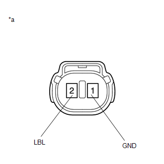
*a | Component without harness connected
(Brake Fluid Level Warning Switch (Brake Booster with Master Cylinder Assembly)) | | |
(b) Reconnect the A34 brake pedal stroke sensor assembly connector.
(c) Remove the brake master cylinder reservoir filler cap assembly.
(d) Make sure that there is no looseness at the locking part and the connecting part of the connector.
OK:
The connector is securely connected.
(e) Disconnect the A4 brake fluid level warning switch (brake booster with master cylinder assembly) connector.
(f) Check both the connector case and the terminals for deformation and corrosion.
OK:
No deformation or corrosion.
(g) Measure the resistance according to the value(s) in the table below.
HINT:
A
float is located inside the brake master cylinder reservoir assembly
(brake booster with master cylinder assembly). Its position changes
according to the level of brake fluid.
Standard Resistance:
|
Tester Connection | Condition |
Specified Condition |
|
2 (LBL) - 1 (GND) | Brake fluid level warning switch (brake booster with master cylinder assembly) off (float up) |
1.84 to 2.16 kΩ |
|
2 (LBL) - 1 (GND) | Brake fluid level warning switch (brake booster with master cylinder assembly) on (float down) |
Below 1 Ω (Brake fluid level is low) |
(h)
If there are no problems after completing the preceding inspection,
adjust the brake fluid to the MAX level with the power switch on (IG).
| NG |
| REPLACE BRAKE BOOSTER WITH MASTER CYLINDER ASSEMBLY |
|
OK | |
| |
| 3. |
CHECK
HARNESS AND CONNECTOR (BRAKE BOOSTER WITH MASTER CYLINDER ASSEMBLY -
BRAKE FLUID LEVEL WARNING SWITCH (BRAKE BOOSTER WITH MASTER CYLINDER
ASSEMBLY)) |
(a) Turn the power switch off.
(b) Make sure that there is no looseness at the locking part and the connecting part of the connector.
OK:
The connector is securely connected.
(c) Disconnect the A35 skid control ECU (brake booster with master cylinder assembly) connector.
(d) Check both the connector case and the terminals for deformation and corrosion.
OK:
No deformation or corrosion.
(e) Measure the resistance according to the value(s) in the table below.
Standard Resistance:
|
Tester Connection | Condition |
Specified Condition |
|
A35-16 (LBL) - A4-2 (LBL) |
Always | Below 1 Ω |
|
A35-16 (LBL) or A4-2 (LBL) - Body ground |
Always | 10 kΩ or higher |
|
A4-1 (GND) - Body ground |
Always | Below 1 Ω |
| NG |
| REPAIR OR REPLACE HARNESS OR CONNECTOR |
|
OK | |
| |
(a) Reconnect the A35 skid control ECU (brake booster with master cylinder assembly) connector.
(b) Reconnect the A4 brake fluid level warning switch (brake booster with master cylinder assembly) connector.
(c) Disconnect the A34 brake pedal stroke sensor assembly connector.
(d)
Perform a road test according to Freeze Frame Data or customer problem
analysis. While driving, check for abnormal brake pedal vibration caused
by brake discs that are worn or have excess runout.
OK:
Brake pedal does not vibrate during braking.
HINT:
| NG |
| REPLACE BRAKE DISC |
|
OK | |
| |
(a) Turn the power switch off.
(b) Reconnect the A34 brake pedal stroke sensor assembly connector.
(c) Clear the DTCs.
Click here
Chassis > ABS/VSC/TRAC > Clear DTCs
(d) Turn the power switch off.
(e) Turn the power switch on (READY).
(f) Perform a road test.
(g) Check if the same DTC is output.
Click here
Chassis > ABS/VSC/TRAC > Trouble Codes
| Result |
Proceed to |
| DTC C120F is not output. |
A |
| DTC C120F is output. |
B |
| A |
| USE SIMULATION METHOD TO CHECK |
| B |
| REPLACE BRAKE BOOSTER WITH MASTER CYLINDER ASSEMBLY |
Open Circuit in ABS Motor Relay Circuit (C146C,C146D)
DESCRIPTION
The ABS motor relay is built into the brake booster with master cylinder assembly.
During
ABS, TRAC, VSC, brake hold, secondary collision brake or brake assist
operation, the skid control ECU (brake booster with master cylinder
assembly) turns on the ABS motor relay to run the pump motor in the
brake actuator assembly.
When any DTC related to
the ABS motor is stored, the IC built into the skid control ECU (brake
booster with master cylinder assembly) operates in fail-safe mode.
When
the supplied voltage to the BM terminal of the ABS motor relay is
excessively low due to an auxiliary battery or charging circuit
malfunction, DTC C146C and/or C146D is stored.
|
DTC No. | Detection Item |
INF Code | DTC Detection Condition |
Trouble Area | MIL |
Note |
| C146C |
Open Circuit in ABS Motor Relay Circuit |
612 | When operation of the ABS motor is requested, the ABS motor voltage is less than 7.6 V for 0.2 seconds or more. |
- Wire harness or connector
- Skid control ECU (brake booster with master cylinder assembly)
- Brake actuator assembly
| Comes on |
- INF Code 612: SAE Code C052E
- ABS DTC
|
| C146D |
Short Circuit in ABS Motor Relay Circuit |
613 | A short in the ABS motor relay drive circuit is detected for 4 seconds or more. |
- Wire harness or connector
- Skid control ECU (brake booster with master cylinder assembly)
- Brake actuator assembly
| Comes on |
- INF Code 613: SAE Code C052D (Case 1)
- ABS DTC
|
MONITOR DESCRIPTION
The skid control ECU (brake booster with master cylinder assembly) monitors the voltage of the ABS motor.
When
the ABS motor relay is instructed to be on and the voltage of the ABS
motor is within the range of an open circuit malfunction, or when the
ABS motor is instructed to be off and the voltage of the ABS motor is
within the range of a short circuit malfunction, an open circuit or
short circuit is judged respectively and the MIL is illuminated and a
DTC is stored.
MONITOR STRATEGY
|
Related DTCs | C052D (Case 1): ABS pump motor circuit high
C052E: ABS pump motor open circuit |
|
Required Sensors/Components(Main) | Brake actuator assembly |
|
Required Sensors/Components(Related) | Skid control ECU (brake booster with master cylinder assembly)
Brake actuator assembly |
| Frequency of Operation |
Continuous |
| Duration |
0.2 seconds: C052E 4 seconds: C052D (Case 1) |
|
MIL Operation | Immediately |
|
Sequence of Operation | None |
TYPICAL ENABLING CONDITIONS
All |
Monitor runs whenever the following DTCs are not stored |
None |
C052E |
Either of the following conditions is met |
A or B |
| A. Both of the following conditions are met |
- |
| ABS pump motor voltage is 7.607 V or more experience |
Not met |
| Command to ABS motor relay |
On |
| B. All of the following conditions are met |
- |
| ABS pump motor voltage is 7.607 V or more experience |
Met |
| Command to ABS motor relay |
On |
| Power supply for ABS motor |
Higher than 9.13 V |
C052D (Case 1) |
Command to ABS motor relay | Off |
TYPICAL MALFUNCTION THRESHOLDS
C052E |
ABS pump motor voltage | Less than 7.607 V |
C052D (Case 1) |
ABS pump motor voltage | 7.607 V or more, and less than 18.57 V |
COMPONENT OPERATING RANGE
C052E |
Both of the following conditions are met |
- |
| Command to ABS motor relay |
On |
| ABS pump motor voltage |
7.607 V or more |
C052D (Case 1) |
ABS pump motor voltage | Less than 7.607 V, or 18.57 V or more |
CONFIRMATION DRIVING PATTERN
- Connect the Techstream to the DLC3.
- Turn the power switch on (IG).
- Turn the Techstream on.
- Clear the DTCs (even if no DTCs are stored, perform the clear DTC procedure).
- Turn the power switch off.
- Turn the power switch on (IG).
- Turn the Techstream on.
- Wait 4 seconds.
- Enter the following menus: Chassis / ABS/VSC/TRAC / Trouble Codes.
- Read the DTCs.
HINT:
- If a DTC is output, the system is malfunctioning.
- If a DTC is not output, perform the following procedure.
- If the DTCs are not output, perform a universal trip and check for permanent DTCs.
Click here 
HINT:
- If a permanent DTC is output, the system is malfunctioning.
- If no permanent DTCs are output, the system is normal.
WIRING DIAGRAM
Refer to DTC C1427.
Click here
CAUTION / NOTICE / HINT
NOTICE:
- After replacing the skid control ECU (brake booster with master cylinder
assembly), perform linear solenoid valve offset learning, ABS holding
solenoid valve learning, yaw rate and acceleration sensor zero point
calibration and system information memorization after performing "Reset
Memory".
Click here
- Inspect the fuses for circuits related to this system before performing the following procedure.
HINT:
When
DTCs C1241 and/or C1417 are output together with C146C and/or C146D,
inspect and repair the trouble areas indicated by C1241 and/or C1417
first.
for C1241: Click here
for C1417: Click here
PROCEDURE
| 1. |
CHECK HARNESS AND CONNECTOR (BM TERMINAL) |
| (a) Make sure that there is no looseness at the locking part and the connecting part of the connector.
OK: The connector is securely connected. |
 |
|
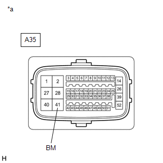
*a | Front view of wire harness connector
(to Skid Control ECU (Brake Booster with Master Cylinder Assembly)) | | |
(b) Disconnect the A35 skid control ECU (brake booster with master cylinder assembly) connector.
(c) Check both the connector case and the terminals for deformation and corrosion.
OK:
No deformation or corrosion.
(d) Measure the voltage according to the value(s) in the table below.
Standard Voltage:
|
Tester Connection | Condition |
Specified Condition |
|
A35-41 (BM) - Body ground |
Always | 11 to 14 V |
| NG |
 | REPAIR OR REPLACE HARNESS OR CONNECTOR (BM CIRCUIT) |
|
OK |
 | |
| 2. |
CHECK HARNESS AND CONNECTOR (BRAKE BOOSTER WITH MASTER CYLINDER ASSEMBLY - BRAKE ACTUATOR ASSEMBLY) |
(a) Make sure that there is no looseness at the locking part and the connecting part of the connector.
OK:
The connector is securely connected.
(b) Disconnect the A39 brake actuator assembly connector.
(c) Check both the connector case and the terminals for deformation and corrosion.
OK:
No deformation or corrosion.
(d) Measure the resistance according to the value(s) in the table below.
Standard Resistance:
|
Tester Connection | Condition |
Specified Condition |
|
A35-40 (+BM) - A39-10 (+BM) |
Always | Below 1 Ω |
|
A35-40 (+BM) or A39-10 (+BM) - Body ground |
Always | 10 kΩ or higher |
| NG |
| REPAIR OR REPLACE HARNESS OR CONNECTOR |
|
OK | |
| |
| 3. |
CHECK HARNESS AND CONNECTOR (GND TERMINAL) |
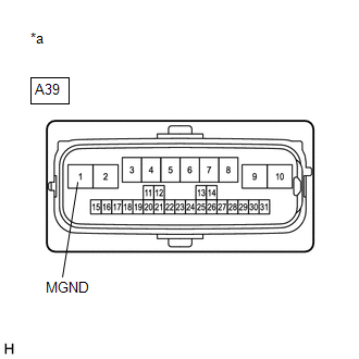
| (a) Measure the resistance according to the value(s) in the table below.
Standard Resistance: |
Tester Connection | Condition |
Specified Condition | |
A39-1 (MGND) - Body ground |
Always | Below 1 Ω | |
 |
|
*a | Front view of wire harness connector
(to Brake Actuator Assembly) | | |
| NG |
| REPAIR OR REPLACE HARNESS OR CONNECTOR (GND CIRCUIT) |
|
OK | |
| |
(a) Reconnect the A35 skid control ECU (brake booster with master cylinder assembly) connector.
(b) Reconnect the A39 brake actuator assembly connector.
(c) Clear the DTCs.
Click here
Chassis > ABS/VSC/TRAC > Clear DTCs
(d) Turn the power switch off.
(e) Turn the power switch on (READY).
(f) Perform a road test.
(g) Check if the same DTC is output.
Click here
Chassis > ABS/VSC/TRAC > Trouble Codes
| Result |
Proceed to |
| DTCs C146C and C146D are not output. |
A |
| DTCs C146C and/or C146D are output. |
B |
HINT:
- If a speed signal of 20 km/h (12 mph) or more is sent to the skid
control ECU (brake booster with master cylinder assembly) with the power
switch on (IG) and the stop light switch assembly off, the ECU performs
self-diagnosis of the motor and solenoid circuits.
- If the normal system code is output (no DTCs are output), slightly
jiggle the connectors, wire harness, and fuses of the skid control ECU
(brake booster with master cylinder assembly).
- If any DTCs are output while jiggling a connector or wire harness from
the skid control ECU (brake booster with master cylinder assembly),
inspect and repair the connector or wire harness.
- The DTCs were probably output due to a bad connection of the connector terminal.
| A |
| USE SIMULATION METHOD TO CHECK |
| B |
| REPLACE BRAKE BOOSTER WITH MASTER CYLINDER ASSEMBLY |


